The cooling system consists of the following components:
1. "Fan Modules" on page 33
2. "Airow" on page 35
3. "Power Supply Cooling System" on page 36
Fan Modules
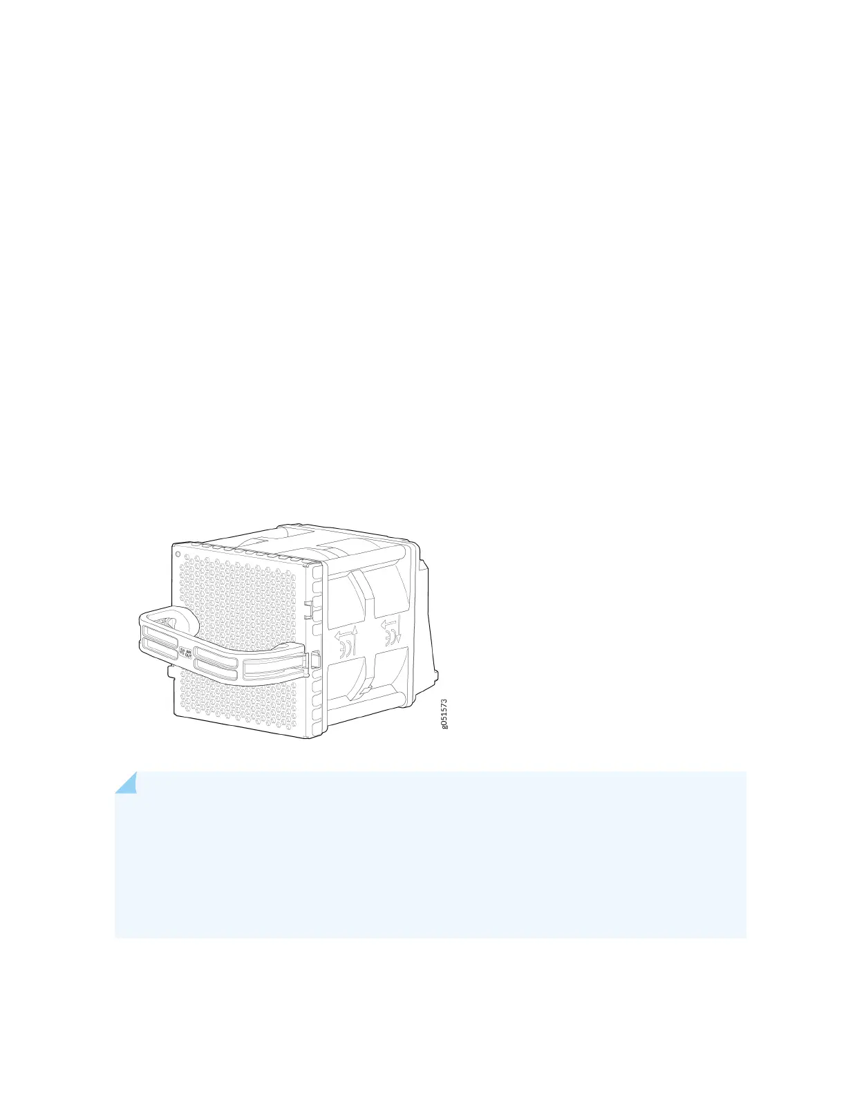
The QFX5240 has four hot-insertable and hot-removable eld-replaceable fan modules (QFX5240-2U-
FANAO) installed at the rear of the switch. Each fan module houses two 80 mm x 80 mm counter-
rotang rotors.
The fan modules in a QFX5240 are FRUs designed for port-to-FRU airow, which is also known as
airow out (AFO) or front-to-back airow. The fan modules are numbered from 0 through 3. Each fan
module is 2-U high and has an associated LED to indicate its status. See Figure 18 on page 33.
Figure 18: Fan Module for QFX5240
NOTE: The fan speed varies based on the temperature of internal components, opcs modules,
and the ambient temperature. The maximum speed at which fans operate depends on the
congured ambient temperature. As the fan speed increases, the power consumed by the fans
increases. As a result, the device consumes more power when the temperature is high because
the fans run faster to maintain the operang temperature of the chassis within the congured
limits.
The QFX5240 switch must operate with all the four fan modules installed. If you need to replace a
faulty fan module, see "Remove a Fan Module from QFX5240 Switches" on page 90.
33