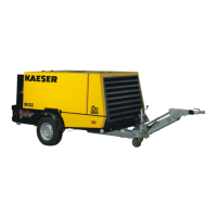
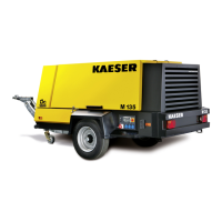
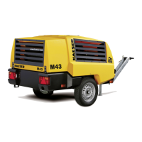
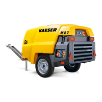
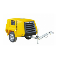
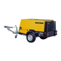
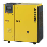
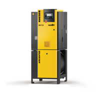
The dimensional drawings also show the position of the following inlets and outlets:
■
Cooling air inlet
■ Cooling air outlet
■ Compressed air outlet
■ Exhaust
2.4 Chassis
2.4.1 Weight
The values given are the maximum in each case. Actual weight of individual machines is depend‐
ent on equipment fitted (see machine nameplate).
Feature Chassis Stationary
Height adjustment with without –
Axle load low high low –
Actual total weight [lb]*
Permissible axle load [lb] 3527 3968 3527 –
* Enter here for reference, the actual total weight taken from the machine nameplate.
Tab. 24 Weight of the machine
2.4.2 Tires
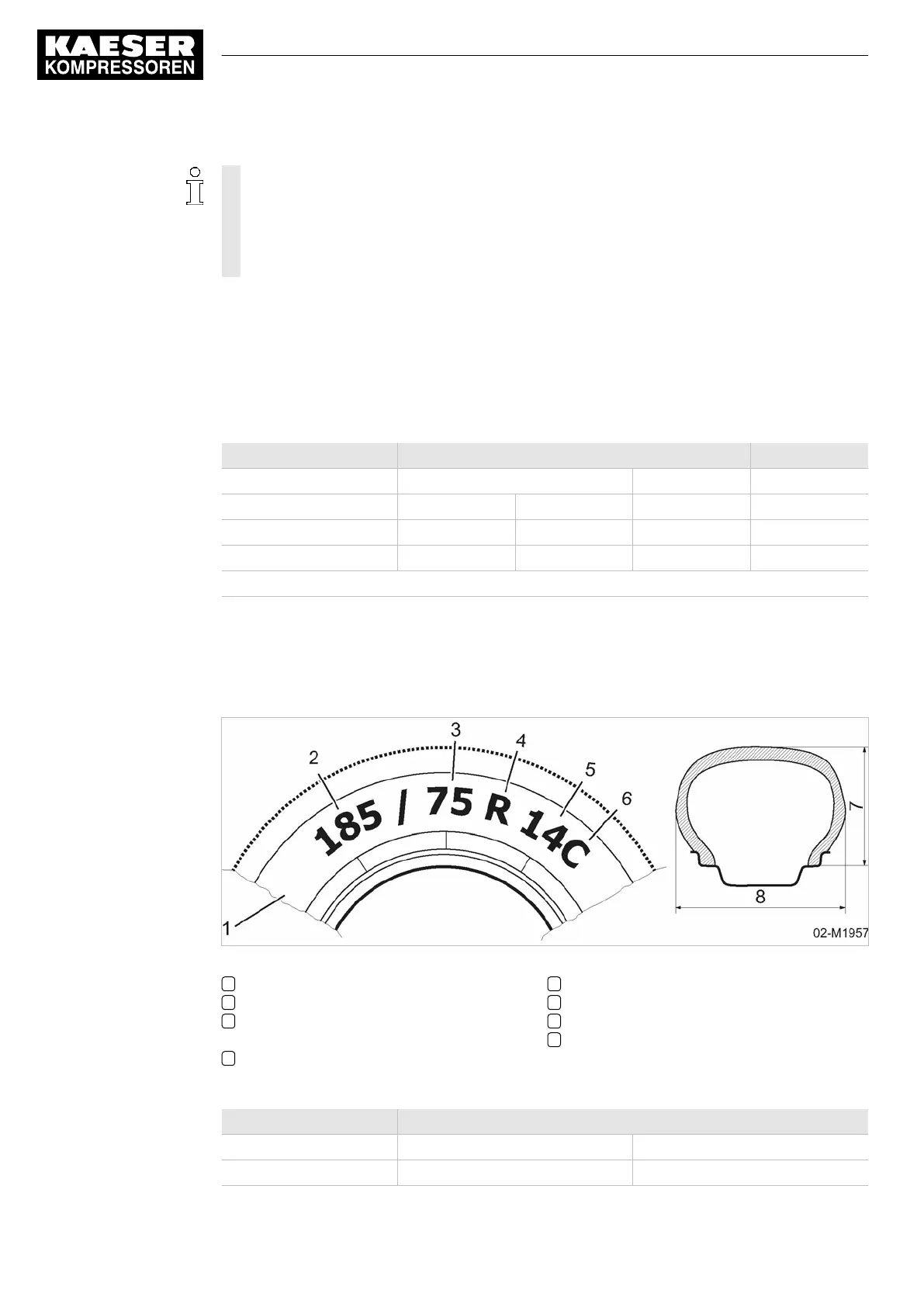
The tire's dimensions are shown on the side wall, see also Fig. 1.
Fig. 1 Example for Tire information on the side wall
1 Section, Tire side wall
2 Tire width [in]
3 Ratio cross-section height to cross-section
width [%]
4 Radial design
5 Rim diameter [in]
6 Light truck Tires (commercial)
7 Cross-section height
8 Cross-section width
Use the following table for detailed information regarding the tires of your machine:
Characteristic/marking Value
Axle load low high
Tire size 185 R 14C 195 R 14C
2 Technical Data
2.4 Chassis
10
Operator Manual Screw Compressor
M100 No.: 9_6999 23 USE


 To Next Page