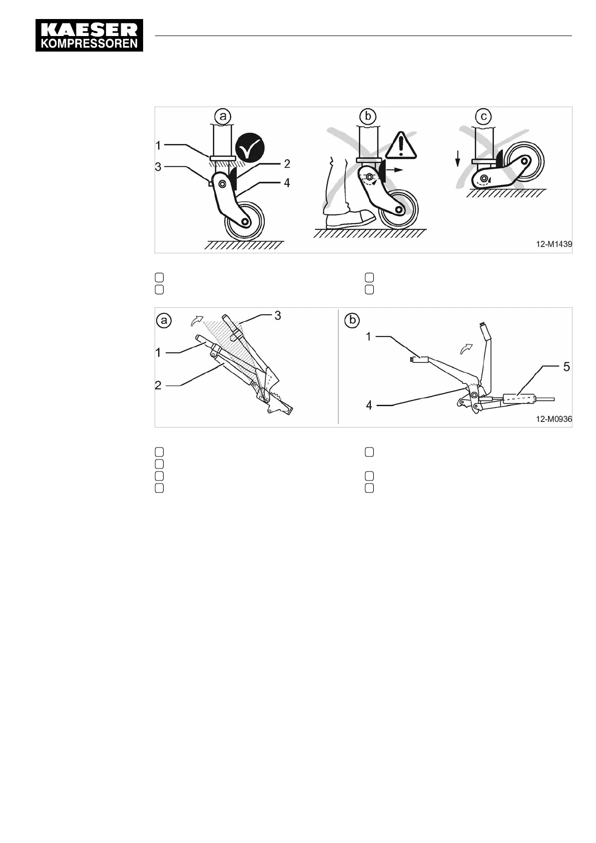
Fig. 103 Towbar with automatic jockey wheel
1 Bead
2 Cam
3 Retaining pin
4 Wheel suspension
Fig. 104 Actuating the parking brake
a Parking brake with gas spring assistance
1 Parking brake lever
2 Gas spring
3 Dead point zone
b Parking brake with ratchet and spring load‐
ing
4 Ratchet
5 Spring loading device
Parking the machine (towing eye coupling):
1.
Use a coupled towing vehicle to move the machine into position.
2. Disconnect the lighting and signaling cable (if provided).
3. Strongly pull the parking brake (if provided) upward past the dead point zone (see Ill.104, fig‐
ure a).
The gas spring holds the brake under tension.
4. Remove the cap nut (if fitted).
5. Lower the jockey wheel until the towing mechanism is stress-free.
6. Place chocks under the wheels.
7. Uncouple the compressor from the towing vehicle:
■ Open the towing coupling of the towing vehicle.
■ Slowly forward the towing vehicle to separate from the parked machine.
Parking the machine (height-adjustable chassis):
1. Use a coupled towing vehicle to move the machine into position.
2. Disconnect the lighting and signaling cable.
12 Decommissioning, Storage and Transport
12.2 Transport
No.: 9_6999 23 USE
Operator Manual Screw Compressor
M100
239
Option rb/rk/rm/rs,
rb/rl/rm/rs

 Loading...


