32
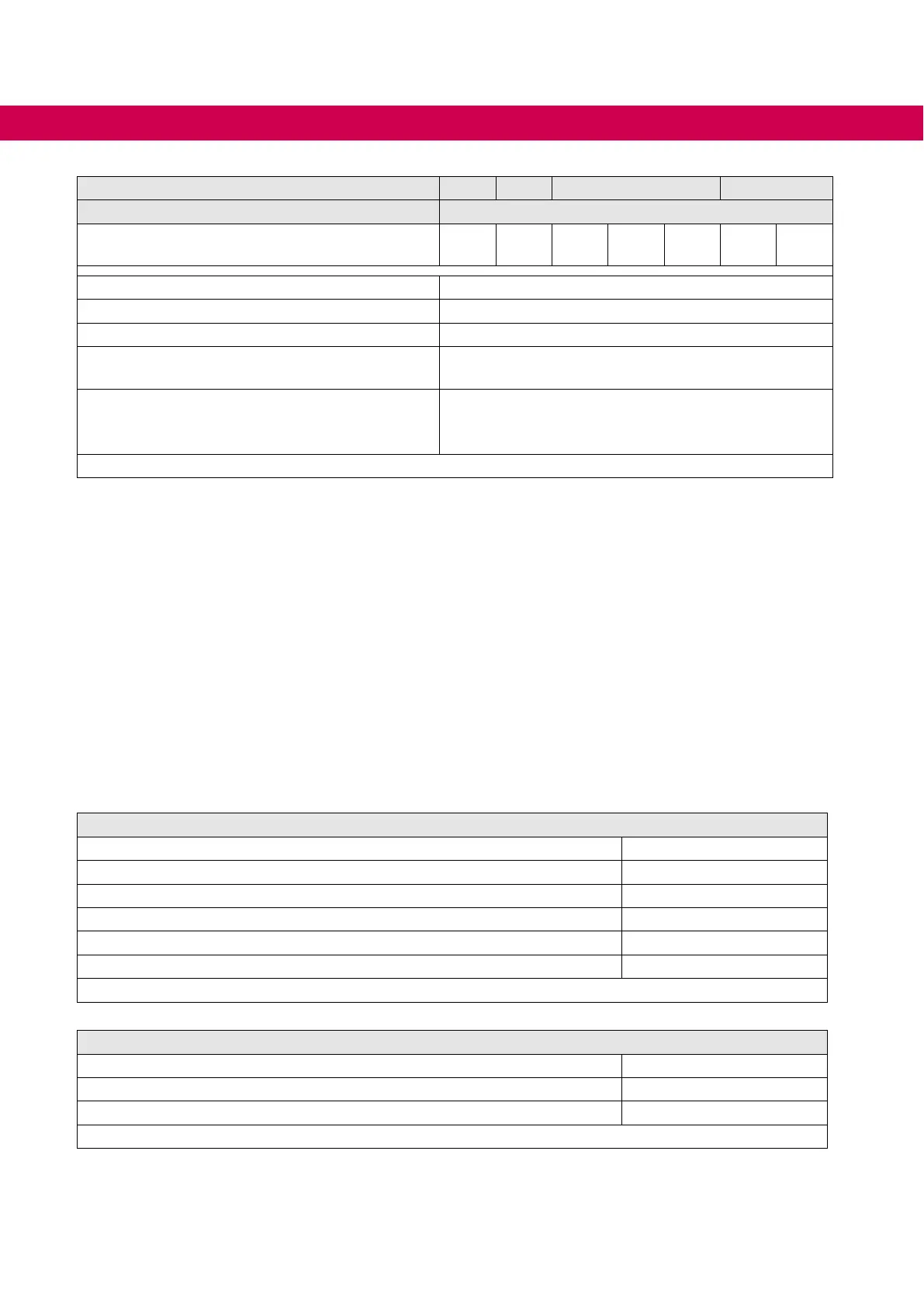
DEVICE DATA OF THE 400 V DEVICES
Device size 21 22 23 24
Housing 6
Maximum current 0Hz / 50Hz at
f
S = 16 kHz
I
out_max
/%
55 /
133
43 /
104
33 /
80
35 /
81
58 /
138
28 /
67
35 /
83
Max. braking current I
B_max / A 168
Min. braking resistor value R
B_min/Ω 5
Braking transistor
6)
Max.cycletime:120s;ED:50%
Protection function for braking
transistor
Short-circuit monitoring
Protection function braking tran-
sistor
(Error GTR7 always on)
8)
Feedback signal evaluation and current shutdown
Table 7: Overview of the 400V unit data
1)
Rated operation corresponds to UN = 400V, rated switching frequency, output frequency = 50 Hz (4-pole
standard asynchronous motor).
2)
The output frequency is to be limited in such a way that it does not exceed 1/10 of the switching frequency.
Devices with higher max. output frequency are subject to export restrictions and are only available on re-
quest.
3)
The values refer in % to the output rated current IN.
4)
Observe limitations „3.2.3.1 Overload characteristic (OL)“.
5)
A detailed description of the derating „3.3.1 Switching frequency and temperature“.
6)
Only available as water-cooled device.
7)
Only available as oil-cooled device.
8)
The feedback signal evaluation monitors the functionality of the braking transistor. The current is switched
o via the internal mains input bridge of the AC supply.
3.2.2 Voltage and frequencies for 400V devices
Input voltages and frequencies
Rated input voltage U
N / V 400
Rated mains voltage (USA) U
N_UL / V 480
Input voltage range U
IN / V 280...550
Input phases 3
Mains frequency f
N / Hz 50 / 60
Mains frequency tolerance ± f
N / Hz 2
Table 8: Input voltages and frequencies of the 400V devices
DC link voltage
DC link rated voltage @ U
N = 400V UN_dc / V 565
DC link rated voltage @ U
N_UL = 480V UN_UL_dc / V 680
DC link voltage working voltage range U
IN_dc / V 390...780
Table 9: DC link voltage for 400V devices

 Loading...


