56
OVERVIEW OF THE COMBIVERT F6
4 Installation and Connection
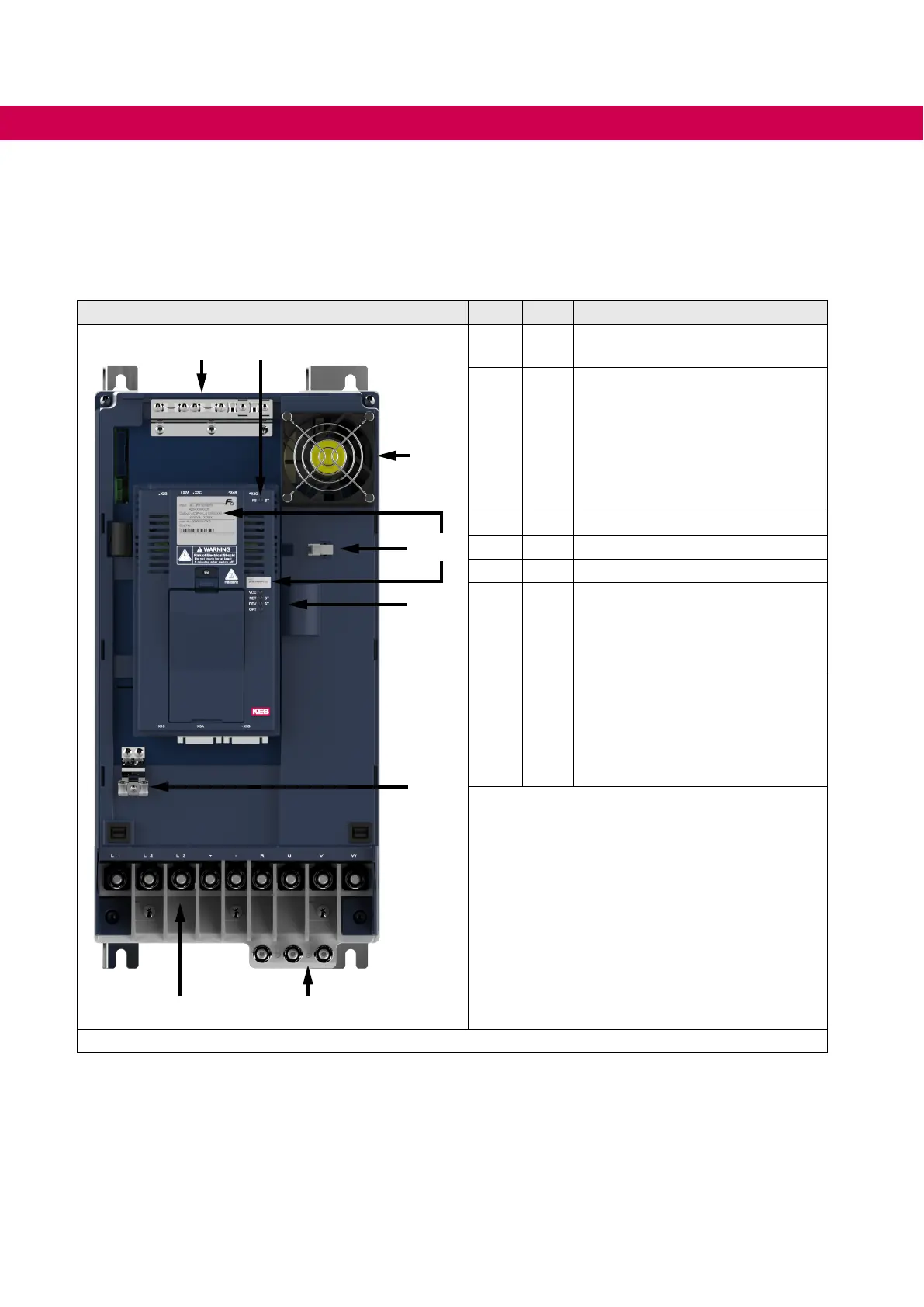
4.1 Overview of the COMBIVERT F6
Housing 6 No.
Name
Description
3
4
2
6
5
1 / 6 ---
Shield clambs for shielded control
cables
2 ---
LEDs (see the manual for control
unit chapter "Overview“)
• For control card COMPACT:
FS without function.
• For control card APPLICA-
TION and PRO: Status indica-
tion of the safety module
3 --- Interior fan
4 --- Connector for the interior fan
5 --- Nameplate
7 PE
Protective earth;
at connection to protective earth
each terminal may be assigned
only once
8 X1A
Power circuit terminals for:
• Mains input
• Braking resistor
• DC supply
• Motor connection
Figure 16: F6 housing 6 top view

 Loading...


