58
OVERVIEW OF THE COMBIVERT F6
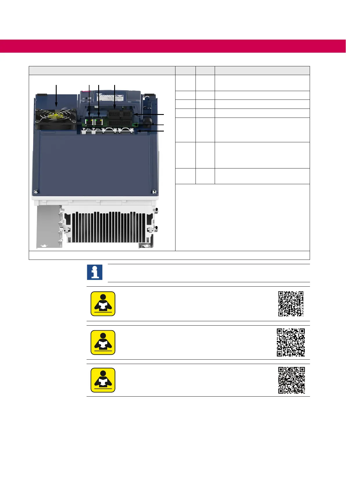
Housing 6 No.
Name
Description
16
17
1
1 ---
Shield clambs for shielded control
cables
3 --- Interior fan
13 X4C Fieldbus interface (out)
14 X4B Fieldbus interface (in)
15 X2C
• CAN bus /
• Analog inputs and
analog output
16 X2B
Safety functions /
24 V DC voltage supply /
2 digital outputs
17 X2A
Control terminal block for digital
inputs and outputs
Figure 18: F6 housing 6 rear view with control board COMPACT
Further information can be found in the respective control board manual.
Instructions for use COMBIVERT F6 control board COMPACT
www.keb.de/leadmin/media/Manuals/dr/ma_dr_f6-cu-k-inst-20144795_en.pdf
Instructions for use COMBIVERT F6 control board APPLICATION
www.keb.de/leadmin/media/Manuals/dr/ma_dr_f6-cu-a-inst-20118593_en.pdf
Instructions for use COMBIVERT F6 control board PRO
www.keb.de/leadmin/media/Manuals/dr/ma_dr_f6-cu-p-inst-20182705_en.pdf

 Loading...


