60
CONNECTION OF THE POWER UNIT
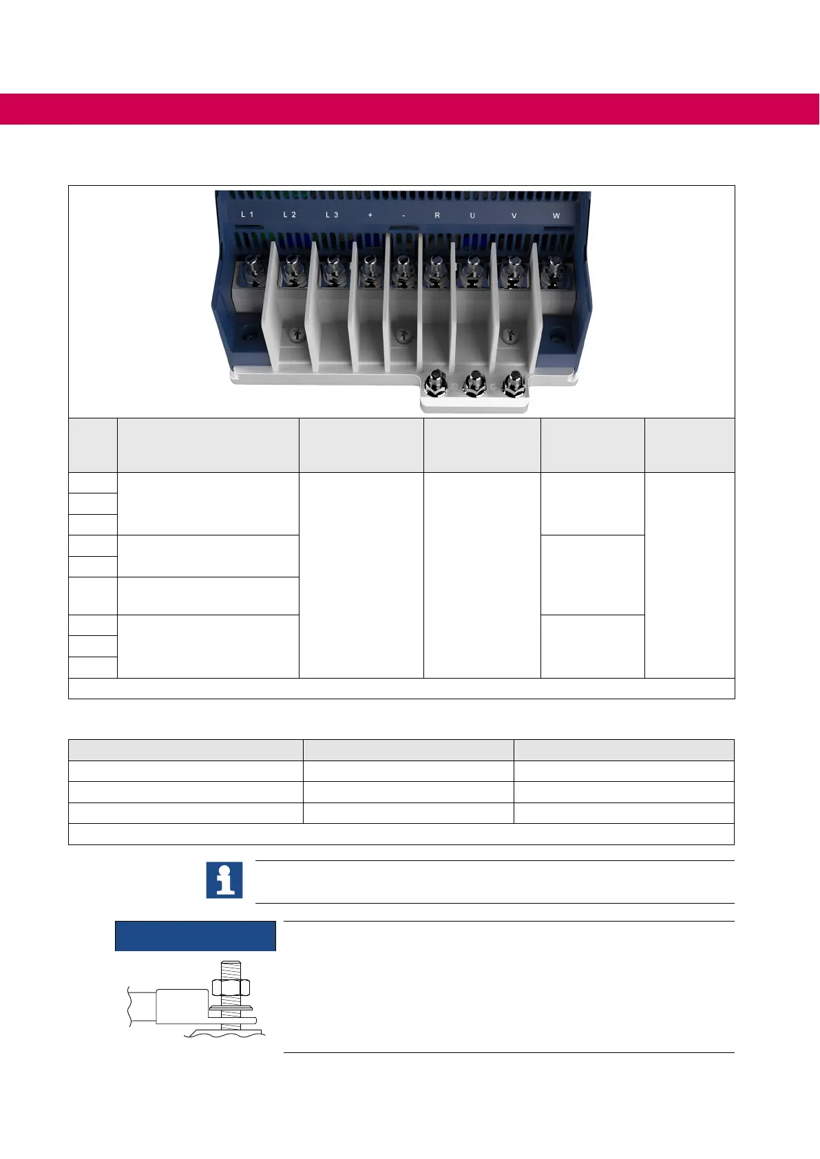
4.2.1.1 Terminal block X1A for 400 V units
Name Function
Terminal connec-
tion
Tightening
torque
Crimp con-
nector dimen-
sion type
Max. num-
ber of con-
ductors
1)
L1
Mains connection
3-phase
8 mm stud for
M8 crimp connec-
tor
10...15 Nm
88...132 lb inch
1
For IEC: 2
For UL: 2
L2
L3
+
DC terminals
2
-
R
Connection for braking re-
sistor (between + and R)
U
Motor connection 1V
W
Figure 20: Terminal block X1A for 400 V devices
1)
From 50mm² only one conductor allowed
Crimp connector dimension Type 1 Type 2
Max. width l / mm 24 19
Max. shaft length l / mm 46 46
Max. diameter l / mm 19 19
Table 30: Crimp connector dimension X1A
Alternatively to a 95 mm² line, 2 parallel 35 mm² lines can also be laid.
NOTICE
Short circuit due too low air and creepage distances!
► The pressing of the crimp connectors must point upwards when
connecting 95 mm² lines!

 Loading...


