4.2.5.8 Connection of the temperature monitoring and brake control (X1C)
A switchable temperature evaluation is implemented in the COMBIVERT.
Therearedierenttypesfortheevaluationavailable.Thesearedependendingonthe
control board => instruction manual „control board“.
The desired operating mode can be adjusted via software (dr33). If the evaluation is
not required, it must be deactivated via software (parameter pn33 = 7) => Programming
manual
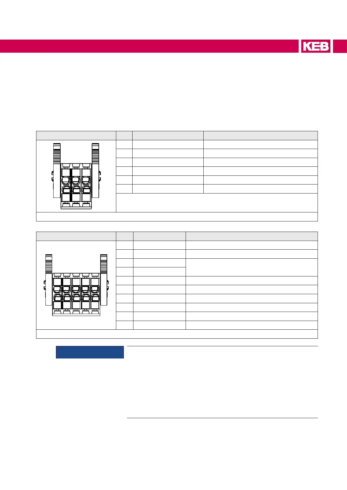
X1C PIN Name Description
1
2
3
4
5
6
1 BR+ Brake control / output +
2 BR- Brake control / output -
3 reserved ―
4 reserved ―
5 TA1 Temperature detection / output +
6 TA2 Temperature detection / output -
Figure 27: Terminal block X1C for control board APPLICATION and COMPACT
X1C PIN Name Description
1
2
3
4
5
6
7
8
9
10
1 BR+ Brake control / output +
2 BR- Brake control / output -
3 0V
For supply of the checkback inputs
4 24Vout
5 DIBR1 Checkback input 1 for brake and relay
6 DIBR2 Checkback input 2 for brake and relay
7 reserved ―
8 reserved ―
9 TA1 Temperature detection / output +
10 TA2 Temperature detection / output -
Figure 28: Terminal block X1C for control board PRO
NOTICE
Malfunctions due to incorrect line or laying!
Malfunctions of the control due to capacitive or inductive coupling.
► Do not route cables from the motor temperature sensor (also shiel-
ded) together with control cables.
► Cables from the motor temperature sensor within the motor cables
may only be used with double shielding!
► The input of the temperature detection has basic isolation.
69
CONNECTION OF THE POWER UNIT

 Loading...


