When a digital input set to "MAN(14)" is activated, the control location P159[0] -
MPRO_REF_SEL = "TERM" switches (switch to "TERM" is not displayed in the
KeStudioDriveManager5). In parallel, the reference source is set to the reference
selected via parameter P164[0] - MPRO_REF_SEL_MAN. The start signal must be
connected to a digital input (ISD0x = Start). The control mode P300[0] - CON_
CfgCon cannot be switched. The "MAN(14)" mode is displayed in the field bus
control word.
It is
not
possible to switch to "MAN" mode
l whenthepowerstageisactive
l whenthedriveintheKeStudioDriveManager5isoperatedviathemanual
modewindow.
A level-triggered START P144[0] - MPRO_DRVCOM_AUTO_START=LEVEL (1) is
ignored in "MAN" mode. After activation of "MAN" mode, the START input must be
reset. When "MAN" mode is ended the motor control also stops.
P No. Index P Name / Setting Unit Function
164 0 MPRO_REF_Sel_MAN Selectionofmotionprofile
OFF(0) Noprofileselected
ANA0(1) ReferencevalueofanalogueinputISA0
ANA1(2) ReferencevalueofanalogueinputISA1
TAB(3) Referencefromtable
PLC_BASIC(4) ProfileviaPLCdefinition
PLC(5) ReferencefromPLC
PARA(6) Referenceviaparameter
DS402(7) ReferenceviaCiA402IEC1131
Sercos(8) ReferenceviaSERCOS
PROFI(9) ReferenceviaPROFIBUS
VARAN(10) ReferenceviaVARAN
TWIN(11) Referenceviaexternaloption"TWINsync"
HYD(12) Hydraulicprofile(software-specific)
Table 9.6: “Control selector switching” parameters
ID No.: 0842.26B.5-01Date: 09.2020
ServoOne- Device Help
308
9 Inputs/Outputs settings
P No. Index P Name / Setting Unit Function
ANA2(13) Profileviaanaloguechannel2(Technology
option)
ANA2(14) Profileviaanaloguechannel3(Technology
option)
ANA2(15) Profileviaanaloguechannel4(Technology
option)
ANA2(16) Profileviaanaloguechannel5(Technology
option)
TCAM(17) Tablecamming(softwarespecific)
Table 9.6: “Control selector switching” parameters (continue)
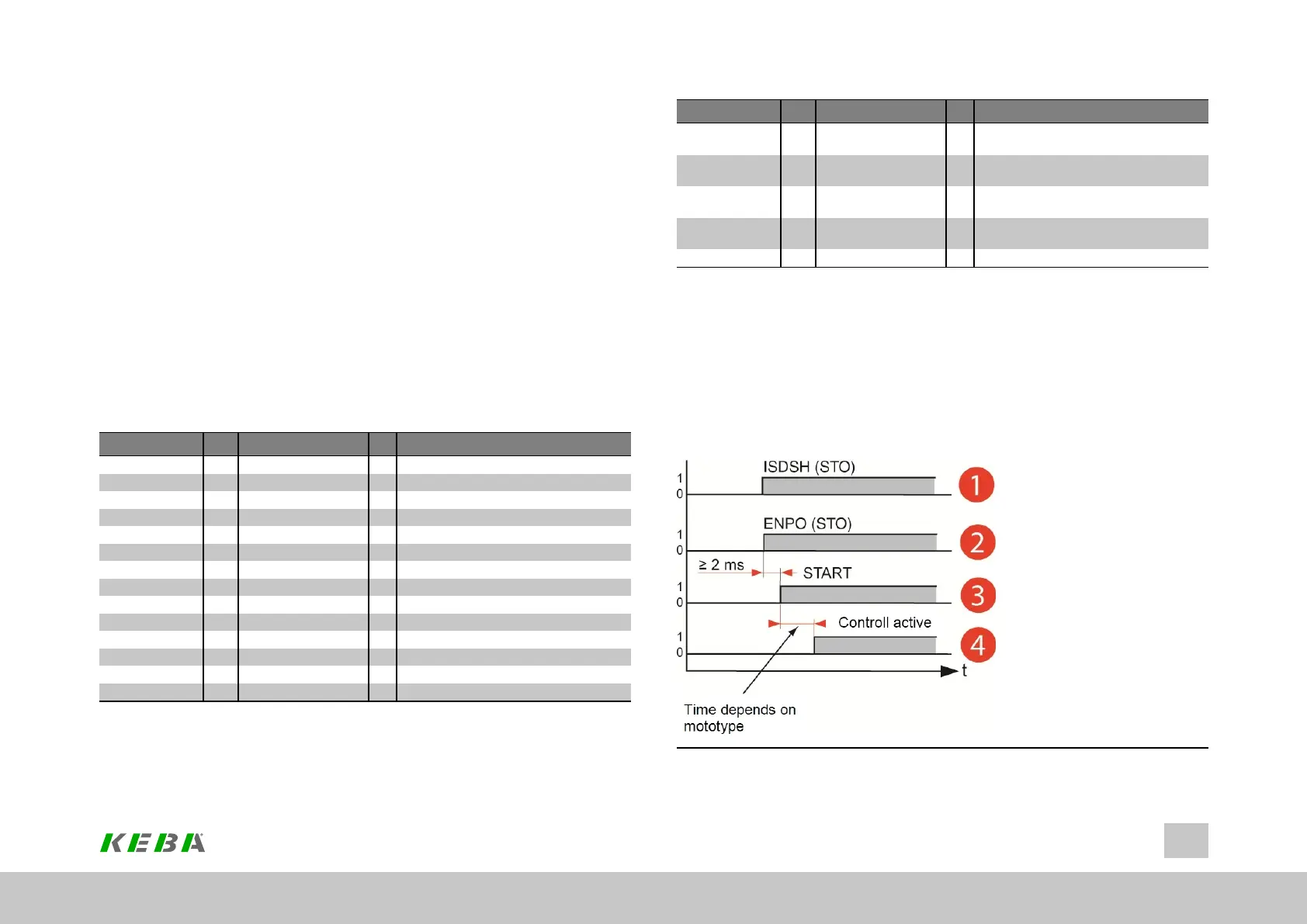
9.2.7Power-upsequence
The power-up sequence must be maintained when the drive starts, regardless of the
control mode. If the power-up sequence is followed, the drive starts with a rising
edge of the digital input parameterized to "START" or when the corresponding "Start"
bit is set via a bus system. The reference polarity determines the direction of rotation.
Image 9.4: Time diagram of sequences
 Loading...


