2400 Series SourceMeter
®
User’s Manual Triggering 11-19
Trigger link
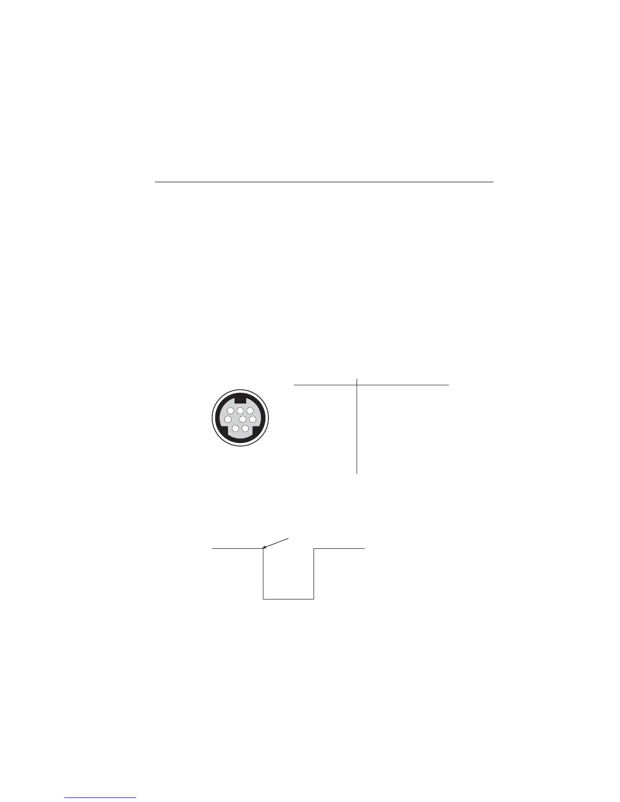
Input and output triggers are received and sent via the rear panel TRIGGER LINK connec-
tor. The trigger link has four lines. At the factory, line #2 is selected for output triggers,
and line #1 is selected for input triggers. These input/output line assignments can be
changed from the CONFIGURE TRIGGER menu. (See “Configuring triggering,” page
11-8.) The connector pinout is shown in Figure 11-5.
Input trigger requirements
An input trigger is used to satisfy event detection for a trigger model layer that is config-
ured for the TRIGGER LINK event. (See “Trigger models,” page 11-30.) The input
requires a falling-edge, TTL compatible pulse with the specifications shown in Figure
11-6.
Figure 11-5
Rear panel pinout
Figure 11-6
Trigger link input pulse specifications
876
5
43
21
Rear Panel Pinout
Pin Number
Description
1
2
3
4
5
6
7
8
Trigger Link 1
Trigger Link 2
Trigger Link 3
Trigger Link 4
Trigger Link 5
Trigger Link 6
Ground
Ground
TTL High
(2V – 5V)
Triggers on
Leading Edge
TTL Low
(≤0.8V)
Artisan Technology Group - Quality Instrumentation ... Guaranteed | (888) 88-SOURCE | www.artisantg.com