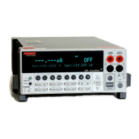
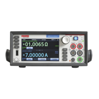
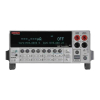
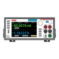
2400 Series SourceMeter
®
User’s Manual Connections 2-3
Remote command terminals selection
Use the :ROUTe:TERMinals (Section 18) command to select the front or rear panel termi-
nals via remote. For example, send the following command to select the rear terminals:
:ROUT:TERM REAR
Conversely, send the following command to choose the front terminals:
:ROUT:TERM FRON
Test fixture interlock
A test fixture interlock switch can be used with the SourceMeter to help protect the DUT.
The SourceMeter output will turn off when the lid of the test fixture is opened. However,
you must ALWAYS assume that power is present until you verify that the SourceMeter
output is off. See Section 13 for details.
Connections to DUT
The maximum allowable voltage differentials between terminals are labeled on the
SourceMeter. Figure 2-1 shows these voltage differentials for the various SourceMeter
models.
WARNING To prevent electric shock and/or damage to the SourceMeter, DO
NOT exceed the maximum allowable voltage differentials shown in
Figure 2-1.
The front and rear terminals of the SourceMeters are rated for con-
nection to circuits rated Installation Category I only. Do not connect
the SourceMeter terminals to CAT II, CAT III, or CAT IV circuits.
Connections of the SourceMeter Input/Output terminals to circuits
higher than CAT I can cause damage to the equipment or expose the
operator to hazardous voltages.
Common mode current limits — As shown in Figure 2-1, the maximum common mode
voltage is the voltage between INPUT/OUTPUT LO and chassis ground. In order to pre-
vent electric shock and/or damage to the SourceMeter, current from an external common
mode voltage source must be limited. Current limiting can be accomplished with the use
of a protective impedance or a fuse.
Artisan Technology Group - Quality Instrumentation ... Guaranteed | (888) 88-SOURCE | www.artisantg.com
 Loading...
