13-6 Digital I/O Port, Safety Interlock, and Output Configuration 2400 Series SourceMeter
®
User’s Manual
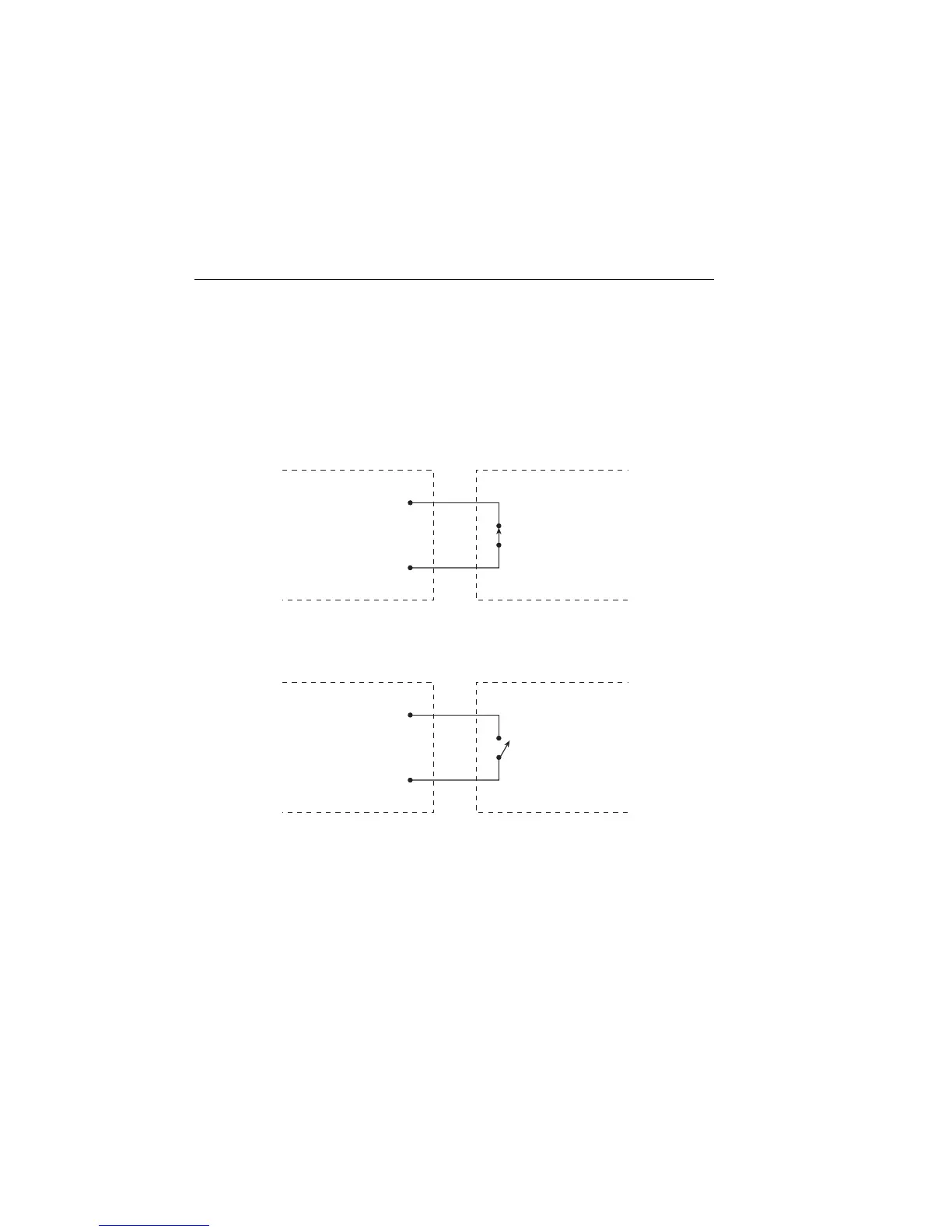
When the interlock is enabled (see “Front panel output configuration,” page 13-7), the out-
put of the SourceMeter cannot be turned on unless the interlock line is pulled low through
a switch to ground as shown in Figure 13-4A. If the lid of the test fixture opens (Figure
13-4B), the switch opens, and the interlock line goes high turning the OUTPUT of the
SourceMeter OFF (high impedance). The output can only be turned back on by first clos-
ing the lid of the test fixture and then pressing the OUTPUT ON/OFF key.
Figure 13-4
Using test fixture interlock
NOTE Safety interlock can be driven by Digital I/O. Allow 100µs settling and response
time. The Digital I/O lines are edge-sensitive, open-collector, and signals should
be debounced to avoid erratic operation.
A. SourceMeter OUTPUT can be turned on.
SourceMeter
/Interlock
(Pin 8)
Interlock-
Digital I/O
GND
(Pin 5 or 9)
Test Fixture
Safety Interlock
Switch (Lid Closed)
B. SourceMeter OUTPUT turns off.
SourceMeter
/Interlock
(Pin 8)
Interlock-
Digital I/O
GND
(Pin 5 or 9)
Test Fixture
Safety Interlock
Switch (Lid Open)
Artisan Technology Group - Quality Instrumentation ... Guaranteed | (888) 88-SOURCE | www.artisantg.com