11-24 Triggering 2400 Series SourceMeter
®
User’s Manual
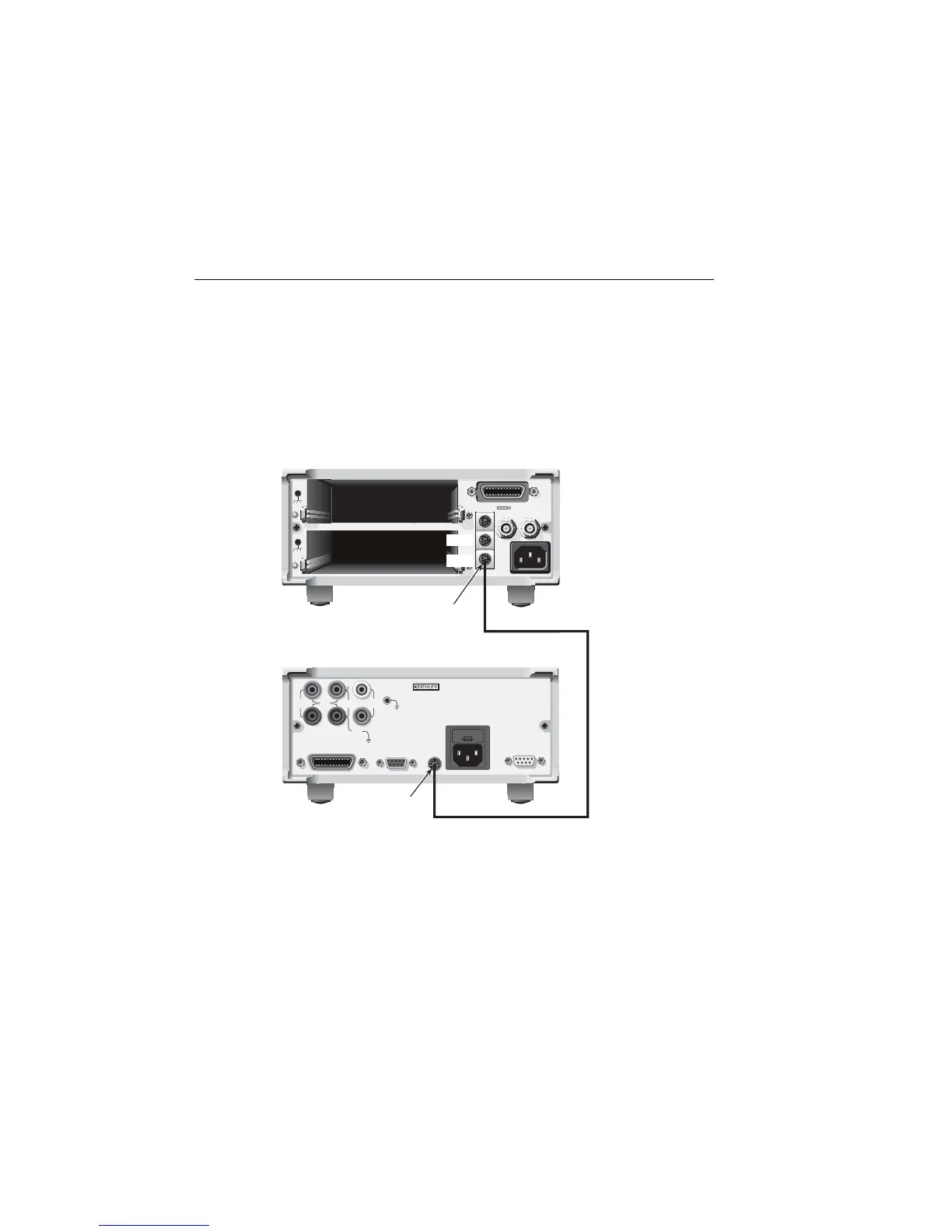
Trigger link connections
The Trigger link connections for this test system are shown in Figure 11-10. Trigger link
of the SourceMeter is connected to Trigger link (IN or OUT) of the switching mainframe.
Note that with the default trigger settings of the switching mainframe, line #1 is an input,
and line #2 is an output.
Figure 11-10
Trigger link connections
WARNING: NO INTERNAL OPERATOR SERVICABLE PARTS, SERVICE BY QUALIFIED PERSONNEL ONLY.
CAUTION: FOR CONTINUED PROTECTION AGAINST FIRE HAZARD, REPLACE FUSE WITH SAME TYPE AND RATING.
MADE IN USA
7001 or 7002 Switch System
SourceMeter
Trigger
Link
Trigger
Link Cable
(8501)
OUT
WARNING: NO INTERNAL OPERATOR SERVICABLE PARTS, SERVICE BY QUALIFIED PERSONNEL ONLY.
CAUTION: FOR CONTINUED PROTECTION AGAINST FIRE HAZARD, REPLACE FUSE WITH SAME TYPE AND RATING.
MADE IN
U.S.A.
INPUT/
OUTPUT
250V
PEAK
250V
PEAK
TRIGGER
LINK
4-WIRE
SENSE
HI
LO
LINE RATING
85-264VAC
50, 60, HZ
70VA MAX
RS232
IEEE-488
(ENTER IEEE ADDRESS
WITH FRONT PANEL MENU)
250V
PEAK
5V
PEAK
5V
PEAK
5V
PK
V, Ω,
GUARD
GUARD
SENSE
LINE FUSE
SLOWBLOW
1A, 250V
INTERLOCK-
DIGITAL I/O
IN
Trigger
Link
Artisan Technology Group - Quality Instrumentation ... Guaranteed | (888) 88-SOURCE | www.artisantg.com