2400 Series SourceMeter
®
User’s Manual Connections 2-5
NOTE To avoid redundancy, generic SourceMeter drawings will be used in this section.
A generic drawing excludes the labeling for the terminal voltage differentials.
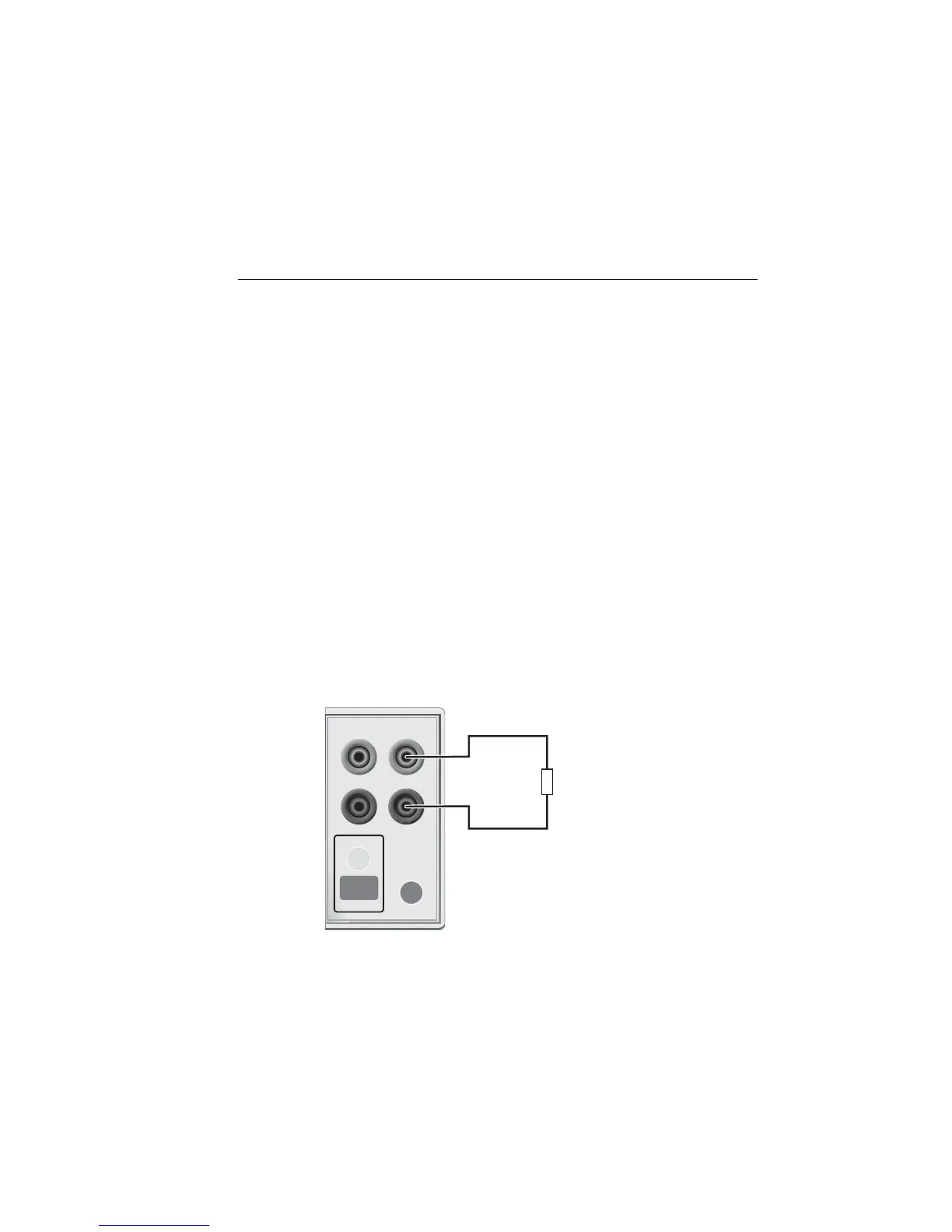
Sensing methods
Basic source-measure operations are performed using either 2-wire local sense connec-
tions (Figure 2-2) or 4-wire remote sense connections (Figure 2-3). The factory default
sense selection is local. See “Sense selection,” page 2-11, to check and/or change the
sense selection. Also, see Section 4 for “Ohms sensing” issues.
WARNING There is no internal connection between earth ground and the selected
INPUT/OUTPUT LO terminal of the SourceMeter. Therefore, hazard-
ous voltages (>30V rms) can appear on that LO terminal. Typically,
this can occur when the SourceMeter is operating in any mode where
the output changes rapidly, such as quick, pulsed waveforms that can
be generated using the ZERO, AUTO-OFF output state, or fast pulse
sweep operations.
To prevent this from occurring (if your application allows it), connect
the INPUT/OUTPUT LO terminal to earth ground. You can connect
the LO terminal to the chassis ground screw terminal on the rear panel,
or to a known safety earth ground. Note that the front panel terminals
are isolated from the rear panel terminals. Therefore, if you are using
the front panel terminals, ground the front panel LO terminal. If using
the rear panel terminals, ground the rear panel LO terminal.
Figure 2-2
Two-wire connections (local sense)
HI
LO
OUTPUT
INPUT/
OUTPUT
4-WIRE
SENSE
ON/OFF
TERMINALS
FRONT/
REAR
DUT
SourceMeter Front Panel
Sense Selection: 2-wire
FRONT/
REAR
Artisan Technology Group - Quality Instrumentation ... Guaranteed | (888) 88-SOURCE | www.artisantg.com