2400 Series SourceMeter
®
User’s Manual Getting Started 1-9
Rear panel summary
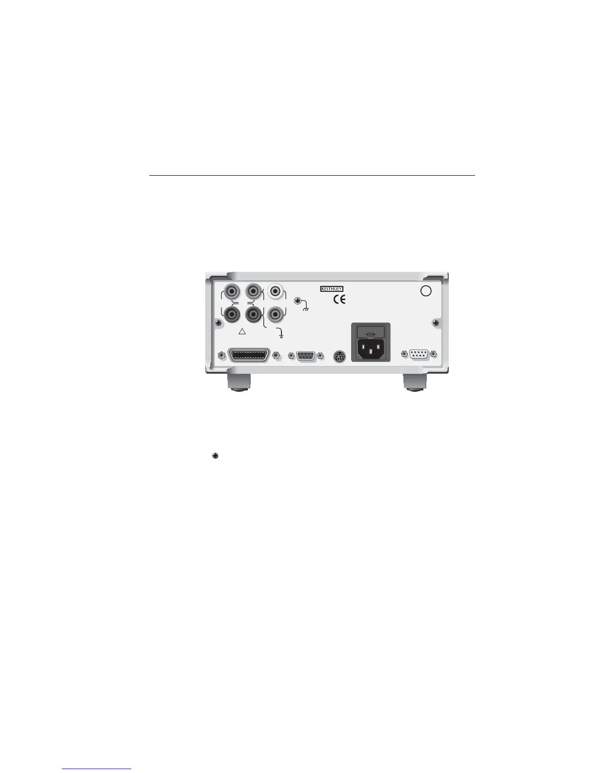
The rear panel of the Model 2400 SourceMeter is shown in Figure 1-2. (The Models 2410,
2420, 2425, 2430, and 2440 are similar.) The following abbreviated information should be
reviewed before operating the instrument.
Figure 1-2
SourceMeter rear panel
Input/output connectors:
INPUT/OUTPUT HI and LO Use to source-measure volts, amps, and ohms.
4-WIRE SENSE HI and LO Use for 4-wire remote sensing.
V, Ω GUARD Driven guard for guarded measurements.
GUARD SENSE Use to correct for IR drops in Guard Output lead.
Earth (chassis) ground screw.
WARNING INPUT/OUTPUT LO is not internally connected to the chassis and
can float up to 250V peak above chassis ground.
Interlock and digital input/output port:
INTERLOCK — DIGITAL I/O Connector for digital output lines, interlock, and component handler
signals. (Output enable on Model 2400 only).
Power module:
Contains the AC line receptacle and the power line fuse.
Trigger link connector:
TRIGGER LINK 8-pin micro-DIN connector for sending and receiving trigger pulses. Use a trigger
link cable or adapter, such as Models 8501-1, 8501-2, 8502, 8504.