E364xA User’s and Service Guide XIX
List of Figures
Figure 1-1 Rear output terminals 5
Figure 1-2 Line voltage selector (set for 115 Vac) 12
Figure 1-3 Front panel 17
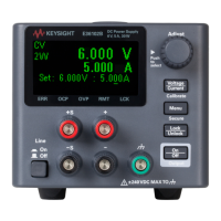
Figure 1-4 Voltage and current limit settings 19
Figure 1-5 Rear panel 20
Figure 1-6 Display annunciators 21
Figure 1-7 Remote voltage sensing connections 26
Figure 2-1 Recommended protection circuit for battery
charging 49
Figure 2-2 DB-9 serial connection 59
Figure 2-3 DB-25 serial connection 60
Figure 3-1 Multiple logical output 108
Figure 3-2 SCPI status system 109
Figure 5-1 Example program result 149
Figure 6-1 Diagram of a simple series power supply 156
Figure 6-2 Block diagram of the power supply showing the remote
interface isolation 157
Figure 6-3 Ideal constant voltage power supply 158
Figure 6-4 Ideal constant current power supply 158
Figure 6-5 Output characteristics 159
Figure 6-6 Simplified diagram of the common mode and normal
mode sources of noise 162
Figure 6-7 Speed of response — programming up (full load) 165
Figure 6-8 Speed of response — programming down 166
Figure 7-1 E364xA dimensions 170
Figure 7-2 E364xA dimensions for rack-mounting 171
Figure 8-1 General disassembly 188
Figure 8-2 Performance verification test setup 193
Figure 8-3 Front or rear panel terminal connections 194
Figure 8-4 CV PARD (ripple and noise) 201
Figure 8-5 Transient response time 203
Figure 8-6 CC PARD connections (ripple and noise) 209