Service and Maintenance 8
Constant Current (CC) Verifications
E364xA User’s and Service Guide 209
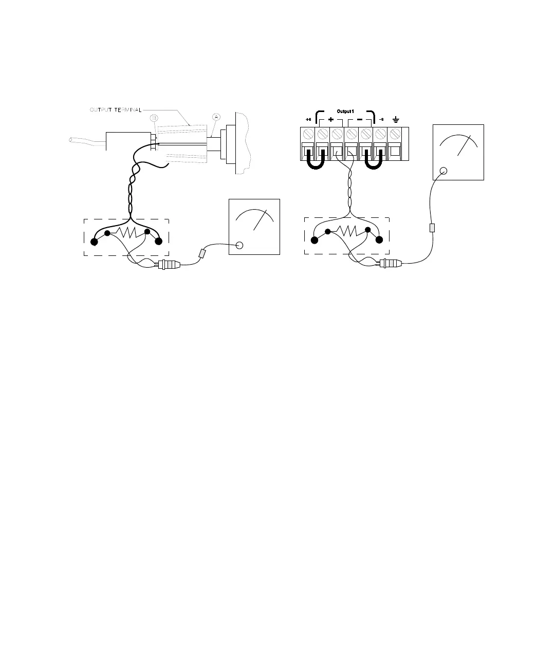
Figure 8-6 CC PARD connections (ripple and noise)
1 Turn off the power supply and connect the output to be
tested as shown in
Figure 8- 6 with the current
monitoring resistor 0.2 Ω (R
M2
) across output terminals.
Connect an rms voltmeter across the current monitoring
resistor as shown in
Figure 8- 6.
2 Turn on the power supply. Select the output to be tested
and the low voltage range (8 V/3 A)
[1]
, enable the output,
and set the display to the limit mode. When the display is
in the limit mode, program the current to the full- scale
rated (3 A)
[1]
and the voltage to the maximum
programmable voltage (8.24 V)
[2]
.
3 Divide the reading on the rms voltmeter by the load
resistance to obtain the rms current. The readings should
be within the limit of 4 mA.
4 Repeat step 1 through step 3 for the other output.
BNC Cable
Input
Rms voltmeter
Rms voltmeter
(Front Panel Connections) (Rear Panel Connections)
Current
Monitoring
Resistor
BNC
Receptacle
Current
Monitoring
Resistor
Split
Ferrites
Input
[1] For the E3646A model. For other models, refer to Tabl e 8 -5 .
[2] For the E3646A model. For other models, refer to Tabl e 7 -3 .