Service and Maintenance 8
Constant Voltage (CV) Verifications
E364xA User’s and Service Guide 201
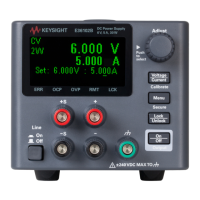
Figure 8-4 CV PARD (ripple and noise)
1 Turn off the power supply and connect the output to be
tested as shown in
Figure 8- 2 to an oscilloscope
(AC coupled) between the (+) and (–) terminals. Set the
oscilloscope to the AC mode and bandwidth limit to
20 MHz. Connect a resistive load (13.5 Ω)
[1]
to the
terminal at B as shown in Figure 8- 4.
BNC Cable
Load Resistor
Input
Rms voltmeter
Rms voltmeter
(Front Panel Connections)
(Rear Panel Connections)
BNC
Receptacle
Split Ferrites*
Input
Load Resistor
For better measurement results, it is recommended to make the
connection between the BNC receptacle and the output terminals as short
as possible, and to use the recommended split ferrites with the
BNC-to-BNC cable as shown in Figure 8-4.
[1] For the E3646A model. For other models, refer to Tabl e 8 -4 .