Networking
P/N 06-237058-001 5-13 February 2012
5-8.9 Remote Positive-Alarm-Sequence (PAS) Events
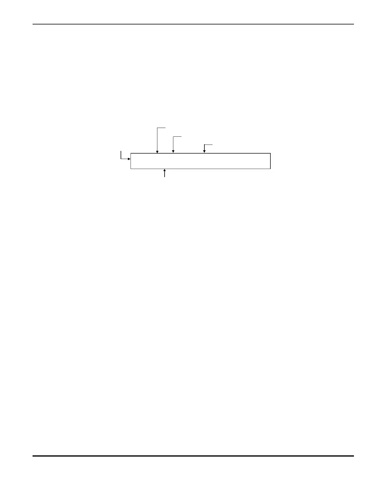
Remote PAS events from a networked control unit are shown in the upper line of the LCD display by:
• Node-of-origin
• Device address
• Change of state
• Device type
The lower line indicates the up-to-40-character message assigned to the alarm-initiating device using
the ARIES NETLink configuration program.
Figure 5-9. Typical Remote PAS Message Display
The following actions also occur when the control unit is configured as Group 0 or when the PAS
event is either from another control unit in the same group as the control unit or from any other
control unit in a network configured for global operation.
1. The internal buzzer pulses
2. The PAS event is stored in the event log
3. The PAS message is transmitted to peripheral devices such as RDCMs, if applicable
4. The PAS message is communicated via the NIC and RS-232 ports, as applicable
Refer to Section 4-10.3.5 for what to do when a Remote PAS Message is Received.
Note: The time remaining on the PAS countdown timer will only appear on the display of the control
unit that received the PAS report from the smoke detector. Remote, networked control units
will not display the PAS countdown timer.
5-8.10 Remote Alarm-Verification Events
Remote alarm-verification events from a networked control unit are shown in the upper line of the
LCD display by:
• Node-of-origin
• Device address
• Change of state
• Device type
The lower line indicates the up-to-40-character message assigned to the alarm-initiating device using
the ARIES NETLink configuration program.
N:01 L1:200 PAS ON PHOTOELECTRIC
FIRST FLOOR LIBRARY
PAS Indication On (Smoke Detectors only)
Device Type Reporting PAS On
Node Number
Device Address L1:200
Device-Specific
Custom Message