Installation
February 2012 2-28 P/N 06-237058-001
2-8.4 Wiring Auxiliary Power Outputs
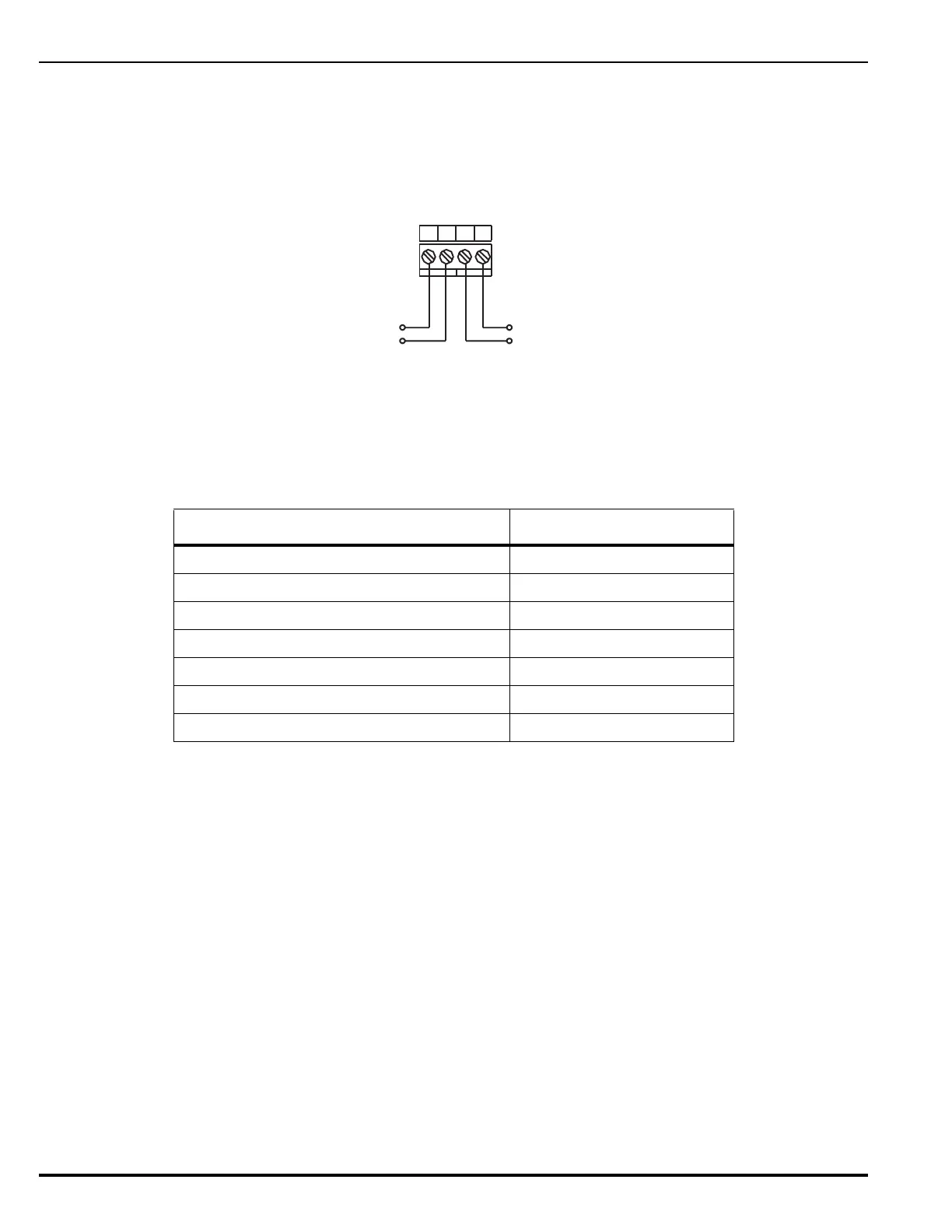
Figure 2-22 shows the auxiliary power terminals on the PMU Board. Both outputs are configurable
for either resettable or non-resettable operation. Both auxiliary power outputs are power-limited.
Each output is special application 19.2 - 27.6 Vdc current, 2.0A @ 470
F (maximum).
Figure 2-22. Auxiliary Power Output Terminals
Note: Table 2-2 lists the Kidde modules which can be powered by AUX power outputs. When using
AUX outputs to drive output power to devices, the total input capacitance of all devices must
be considered. Do not exceed the maximum input capacitances for the modules listed in
Table 2-2:
2-8.5 Wiring Signaling Line Circuits
The Signaling Line Circuit (SLC) is the communications path between the ARIES NETLink control
unit and the SmartOne and associated field devices. The SLC can accommodate any combination of
up to 255 addressable devices, which include SmartOne automatic initiating devices, monitor
modules, relay modules, and control modules.
The SLC can be wired to meet the following NFPA 72 wiring requirements:
• CLASS-A (Loop Isolators optional)
• CLASS-A, Style 7 (Loop Isolators required)
•CLASS-B
Note: All SLC wiring must be twisted, unshielded, low-capacitance, fire-alarm-system wire. Refer to
Appendix B, Wiring Requirements for ARIES NETLink Signaling Line Circuits for
recommended wire types.
Table 2-2. Auxiliary Power Maximum Input Capacitances
Module
Max. Input Capacitance (F)
Addressable Signal/Sounder Module (ASM)
100
Remote Release Module (RRM)
220
Remote LED Annunciator Module (R-LAM)
100
Remote Display Control Module (RDCM)
100
Model ATM-L Annunciator Driver Module
100
Model ATM-R Relay Driver Module
100
Fiber Optic Converter Module (FOCM)
100
-
+
-
+
+
-
-
+
Output No. 1
Output No. 2
J9
AUX-1 AUX-2