General Information
February 2012 1-12 P/N 06-237058-001
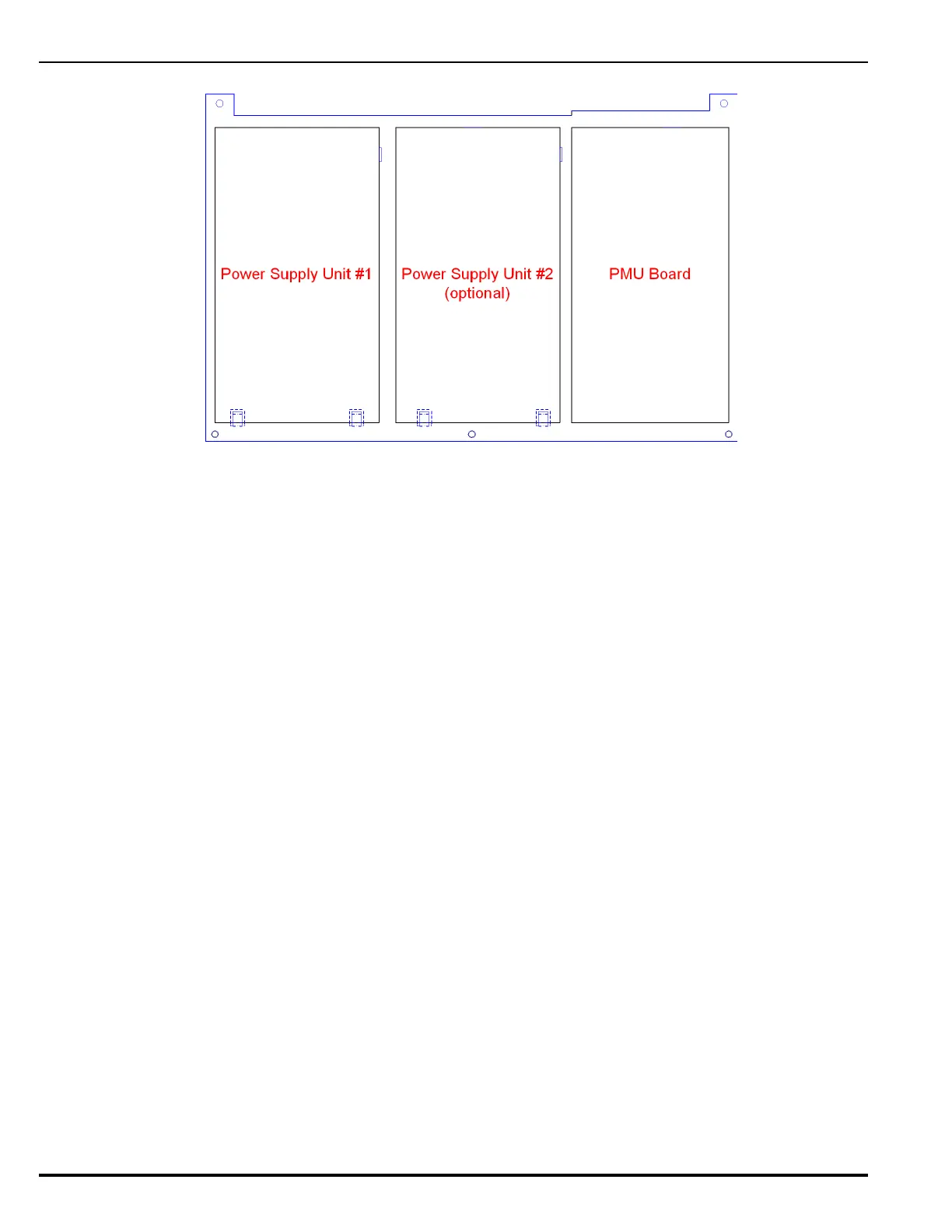
Figure 1-8. Power Supply/PMU Assembly Layout (shown without wiring harnesses)
1-10.1 Power Supply Units
An AC-to-DC switching power supply unit provides a total filtered output of 5.4 A @ 27 Vdc to support
the basic ARIES NETLink system and its associated devices and to charge standby batteries. The
power supply unit is user-configurable for either 120 Vac or 220/ 240 Vac, 50/60 Hz line voltage
(switch located on side of power supply). A second power supply unit can be added to the Power
Supply Assembly to provide a total output capacity of 10.8 A @ 27 Vdc. Refer to Appendix A, Battery
and Power Supply Calculations, to determine battery and power supply needs.
Note: A fully expanded ARIES NETLink system can accommodate a maximum of eight power
supply units (with each pair controlled by a PMU Board).
1-10.2 Power Management Unit (PMU) Board
The PMU Board, shown in Figure 1-9, is an electronic assembly that provides:
• Battery charging and supervision: The PMU Board can charge standby batteries of up to 165-
AH capacity for UL applications and 132-AH capacity for ULC applications. The board can supply
charging voltage of 27.0 Vdc (nominal) with a 4.0 Amp charging circuit current (using a single
power supply) or 8.9 Amp current (using dual power supplies) respectively. The battery bank is
constantly supervised for correct voltage and polarity. If there is more than one PMU board in a
system, only one PMU Board will be responsible for charging, but all will supervise. Charging
current is turned on if the battery charge current falls below maximum acceptable amplitude and
is turned off if the battery charge current exceeds this limit.
• AC power supervision: AC primary power is constantly supervised and its condition reported
to the Main Controller Board. In the event of a loss or reduction of AC power, the PMU Board
automatically switches to standby batteries.
• 24 Vdc supervision: The PMU Board regulates all internal DC power required for the system
electronics from the 27.4 Vdc power and reports back to the Main Controller Board.
• 24 Vdc ground fault detection: The PMU Board can detect if any system ground referenced
external wiring is shorted to building Earth Ground. The amplitude of the ground fault offset is
measured and reported to the Main Controller Board.
•Auxiliary 24 Vdc outputs: Two auxiliary output connectors, rated for 2 A @ 24 Vdc, are
provided.