Networking
February 2012 5-14 P/N 06-237058-001
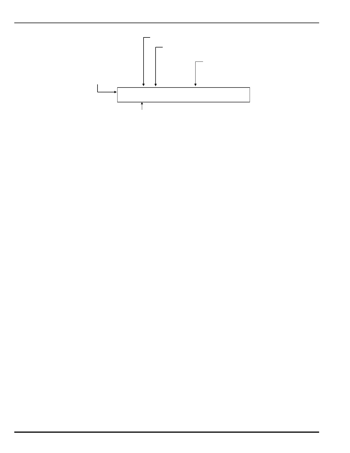
Figure 5-10. Typical Remote Alarm-Verification Message Display
The following actions also occur when a control unit is configured as Group 0 or when the alarm-
verification event is either from another control unit in the same group as the control unit or from
any other control unit in a network configured for global operation.
1. The internal buzzer pulses
2. The alarm-verification event is stored in the event log
3. The alarm-verification message is transmitted to peripheral devices such as RDCMs, if
applicable
4. The alarm-verification message is communicated via the NIC and RS-232 ports, as
applicable
Refer to Section 4-10.3.6 for what to do when a remote alarm-verification message is received.
Note: The time remaining on the alarm-verification timer will only appear on the display of the
control unit that received the verification report from the smoke detector. Remote, networked
control units will not display the alarm-verification timer.
5-8.11 Remote Supervisory Events
Remote supervisory events from a networked control unit are shown in the upper line of the LCD
display by:
• Node-of-origin
• Device address
• State change
• Device type
The lower line indicates the up-to-40-character message assigned to the device using the ARIES
NETLink configuration program.
N:04 L1:010 VERIFY ON PHOTOELECTRIC
CONTROL ROOM
Alarm-Verification Indication On
(Smoke Detectors only)
Device Type Reporting
Alarm-Verification On
Node Number
Device Address L1:010
Device-Specific
Custom Message