Installation
P/N 06-237058-001 2-39 February 2012
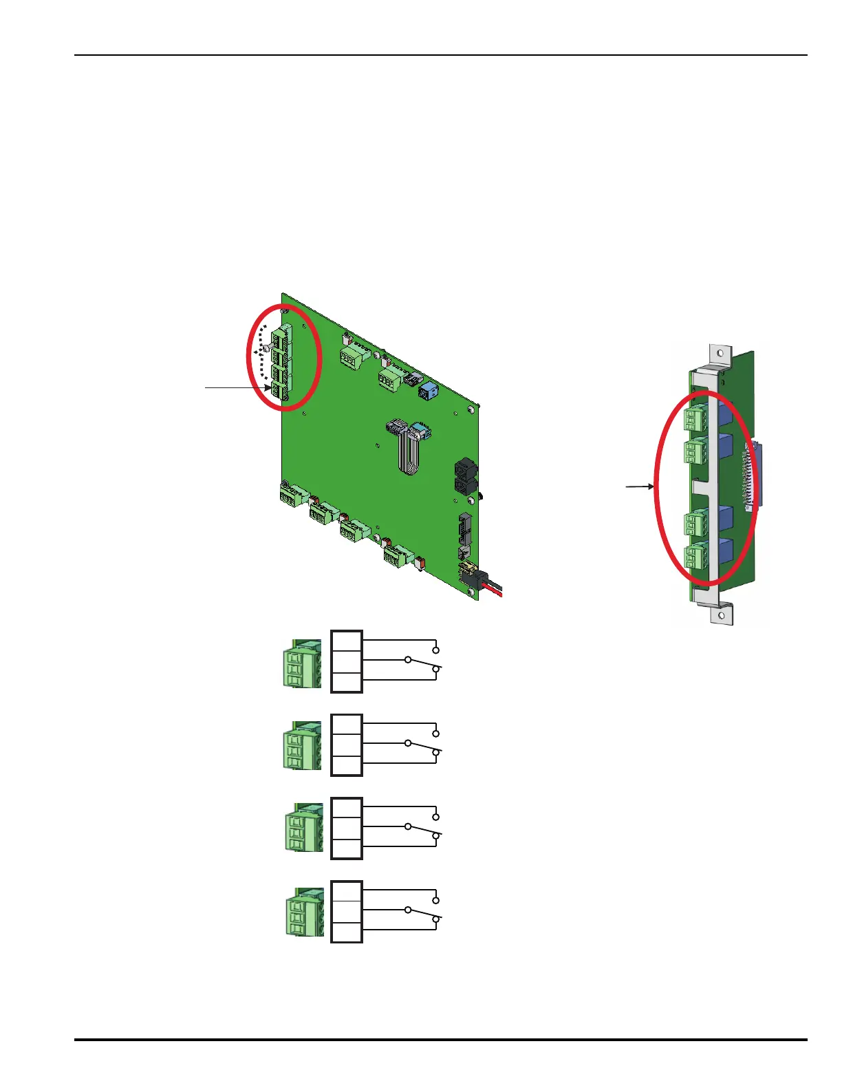
2-8.8 Relay Outputs
The Main Controller Board includes three Form-C, programmable relays and one Form-C, dedicated
Trouble relay. All of these relays have the following contact ratings:
• 3.0 A @ 24 Vdc (resistive)
• 3.0 A @ 120 Vac (resistive)
The Relay Expansion Card includes four Form-C, programmable relays as shown in Figure 2-32. All
of these relays have the same contact ratings listed above. Refer to Section 2-7.2, Inserting and
Securing an Expansion Card for instructions on how to install the Relay Card.
Figure 2-32. Relay Outputs Diagram
1. All relay outputs shown in normal standby condition.
2. All contacts are dry contact type.
3. Outputs of all relays are not supervised.
4. Ratings - 3 Amps @ 30 Vdc or 3 Amps @ 120 Vac.
5. Maximum of one 12 AWG wire per terminal.
Installation Note:
C
NO
NC
RELAY 1
C
NO
NC
C
NO
NC
C
NO
NC
RELAY 2
RELAY 3
RELAY 4
On-board Field-Configurable
Relays (3)
On-board Dedicated
Trouble Relay (1)
TB1
TB2
TB3
TB4
M
a
i
n
C
o
n
t
ro
l
l
e
r
B
o
a
r
d
Relays (located on MCB and Relay Expansion Card)
Relay 1
Relay 2
Relay 3
Relay 4
Field-Configurable
Relays (4)