EasyManuals Logo

Kidde Fire Systems ARIES NETLink User Manual

Kidde Fire Systems ARIES NETLink
294 pages
To Next Page IconTo Next Page
To Previous Page IconTo Previous Page
Page #75 background imageLoading...
Page #75 background image
Installation
P/N 06-237058-001 2-19 February 2012
2-5 MAKING INTERNAL 24VDC POWER CONNECTIONS
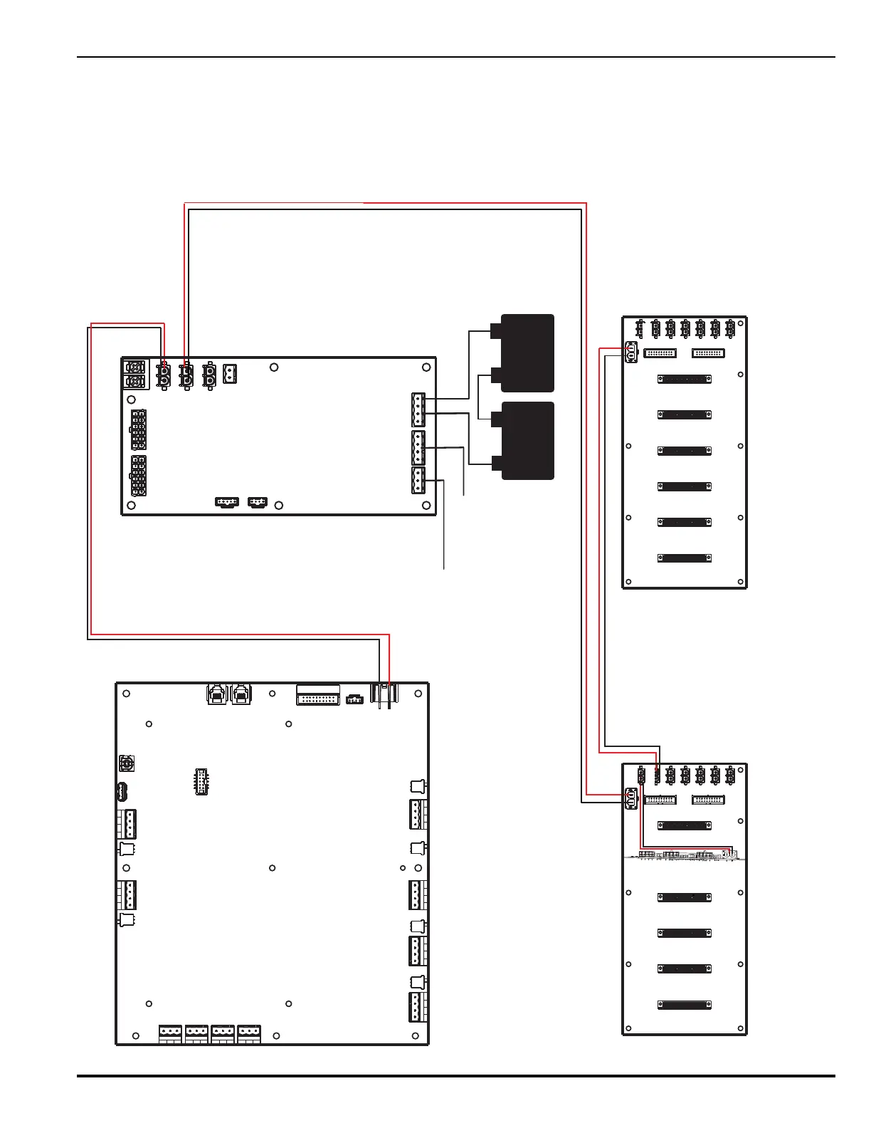
Figure 2-15 provides an overview of internal 24Vdc power supply connections for the ARIES
NETLink system.
Note: Output connectors are white; input connectors are black. All connectors are keyed for correct
orientation when inserted.
Figure 2-15. Internal 24 Vdc Power Connections
12
V
Battery
12
V
Battery
+
-
+
-
Card Cage Backplane
Additional Card Cage Backplane
PMU Board
Main Controller Board
R-NAC Card
J10
J3
J4
J9
J10
J5
J9
J9
J12
J13
J12
J13
AUX Power
Outputs
J11
PMU Trouble Sounder
Relay

Table of Contents

Questions and Answers:

Question and Answer IconNeed help?

Do you have a question about the Kidde Fire Systems ARIES NETLink and is the answer not in the manual?

Kidde Fire Systems ARIES NETLink Specifications

General IconGeneral
BrandKidde Fire Systems
ModelARIES NETLink
CategoryControl Unit
LanguageEnglish

Related product manuals