Installation
February 2012 2-50 P/N 06-237058-001
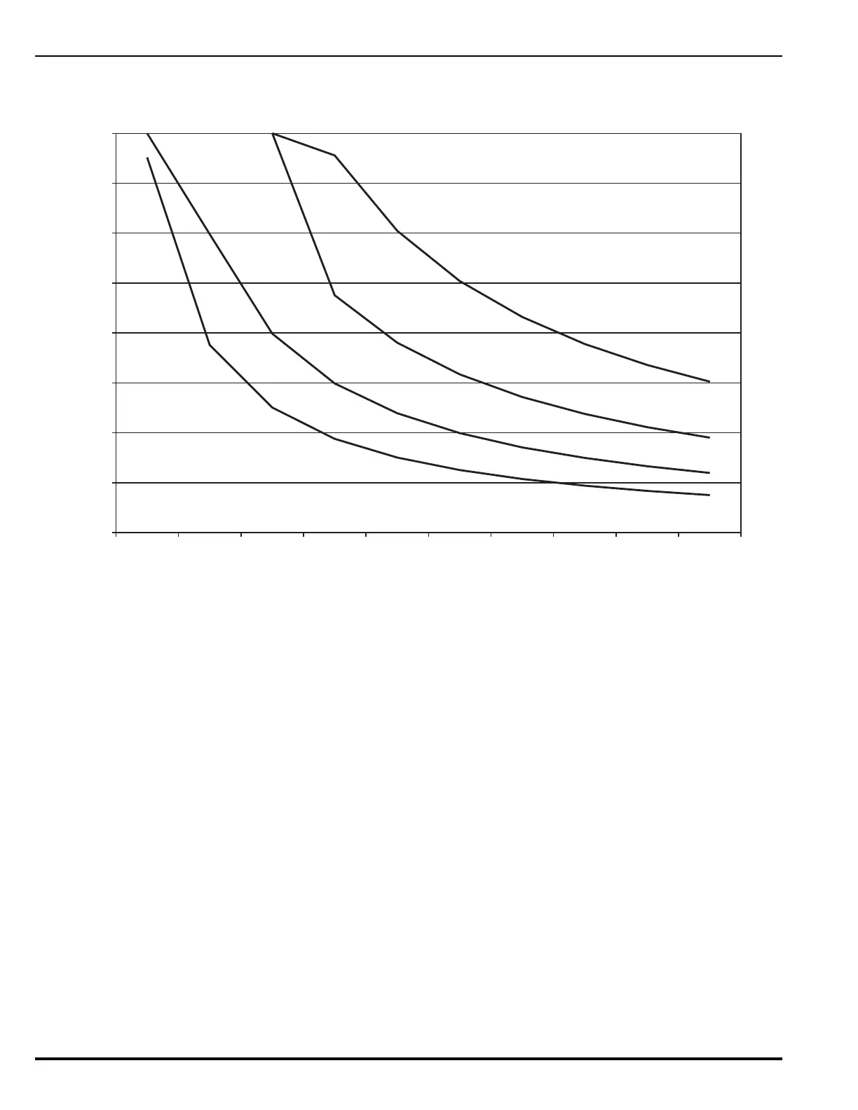
Use Figure 2-42 to estimate the maximum length of wire that can be connected to RS485 peripheral
devices.
Figure 2-42. 24 Vdc-Power Wiring Length vs. Peripheral-Devices Current
2-12.2 Installing the ATM-L Annunciator Driver Module
Refer to the ATM-L/R Series Drivers Installation Manual, P/N 06-236179-002, for instructions on
installing this driver module.
2-12.3 Installing the ATM-R Relay Driver Module
Refer to the ATM-L/R Series Drivers Installation Manual, P/N 06-236179-002, for instructions on
installing this driver module.
2-13 SETTING UP NETWORK EQUIPMENT
2-13.1 Network Interface Card (NIC)
The Network Interface Card contains the circuitry for data communications between networked
control units. One NIC must be installed in the Card Cage of each networked control unit (referred
to as “nodes”). The nodes transmit and receive messages via RS485 communications. Refer to
Section 2-7.2, Inserting and Securing an Expansion Card for instructions on how to install the NIC
Card.
Note: At the originating NIC in the network, attach the earth ground wire behind the bottom NIC
Card mounting screw. NOTE: A ring terminal may be soldered or crimped to the end of the
wire for easier attachment under screw.
0
500
1000
1500
2000
2500
3000
3500
4000
0.1 0.2 0.3 0.4 0.5 0.6 0.7 0.8 0.9 1.0
Total Current (A) for RS-485 Peripheral Devices
0.0
#18 AWG
#16 AWG
#14 AWG
#12 AWG
Maximum Distance (Ft.)