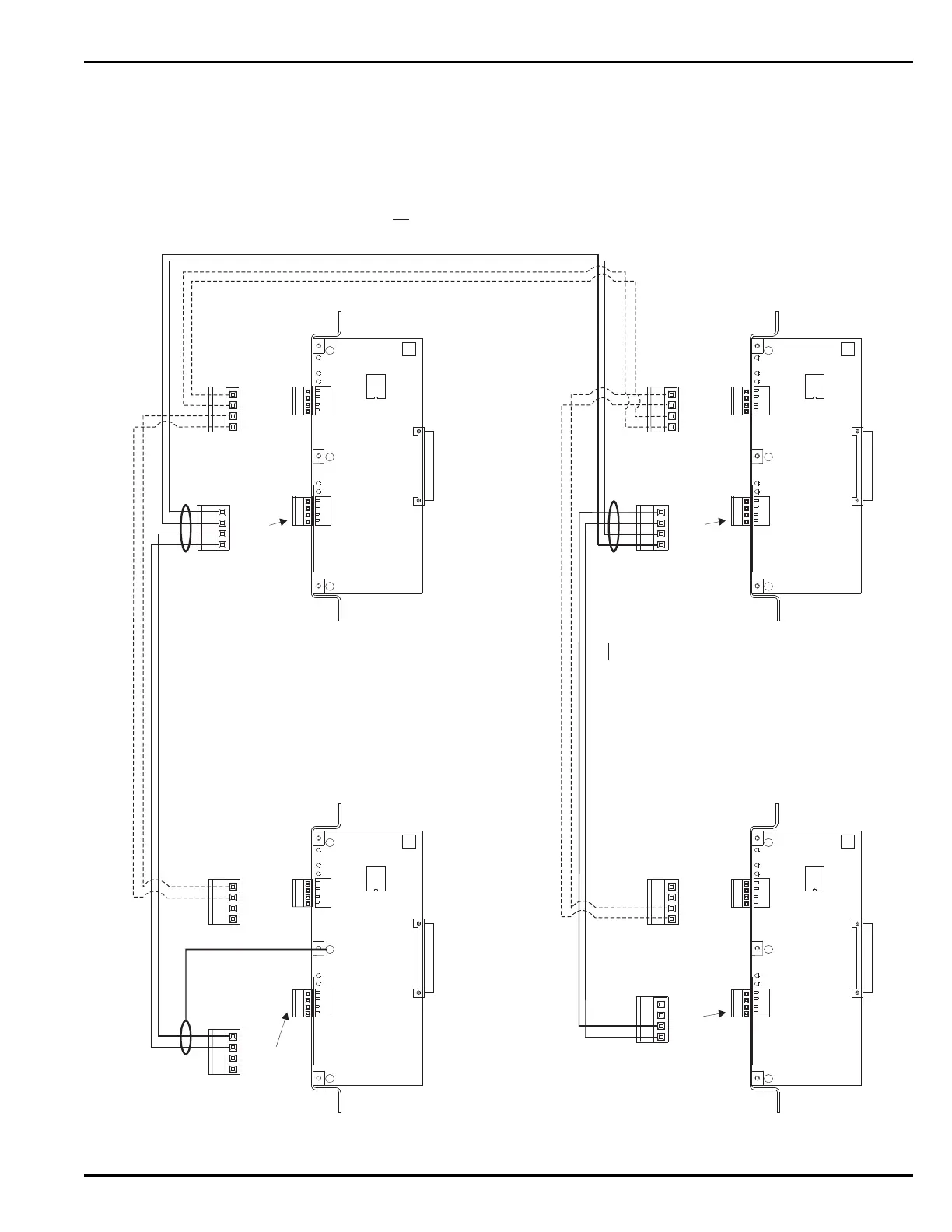
Figure 2-43. Network Interface Card Wiring
Maximum 4,000 Ft of Wire (#1
8
AWG or larger) between Control Units
(Twisted, Shielded, Low-Capacitance Wire)
Node 1
Notes:
1.
Do not T-Tap the network wiring.
Use daisy-chained wiring style only.
2. Do not daisy chain wiring back from
Node N to Node 1.
Connect wires for shields together at each
intermediate NIC. Do
not
connect wires for
shields to the earth-ground screw in
upper-left-hand corner of intermediate NICs.
Leave shield wire floating at last NIC. Do not connect wire for
shield to the earth-ground screw in upper-left-hand
corner of last NIC. Trim shield wire as much as possible.
Note: All wiring is power-limited and supervised.
KIDDE-FENWAL, INC.
ASHLAND, MA 01721
CH2-IN LED
CH2-OUT LED
CH1-IN LED
CH1-OUT LED
J12
J13
J12
Node 2
KIDDE-FENWAL, INC.
ASHLAND, MA 01721
CH2-IN LED
CH2-OUT LED
CH1-IN LED
CH1-OUT LED
J12
KIDDE-FENWAL, INC.
ASHLAND, MA 01721
CH2-IN LED
CH2-OUT LED
CH1-IN LED
CH1-OUT LED
J12
Node 3
KIDDE-FENWAL, INC.
ASHLAND, MA 01721
CH2-IN LED
CH2-OUT LED
CH1-IN LED
CH1-OUT LED
J12
Node N
CH1
CH2
J12
J13
CH1CH1
CH2
J12
J13
CH1
CH2
J12
J13
CH1
CH2
J13
J13
A2
B2
A2
B2
J13
J13
3. Dashed line represents wiring required
for Class A Style 7.
A1
B1
A1
B1
A2
B2
A2
B2
A1
B1
A1
B1
IN
OUT
}
}
IN
OUT
}
}
A1
B1
A1
B1
IN
OUT
}
}
A2
B2
A2
B2
IN
OUT
}
}
A1
B1
A1
B1
A2
B2
A2
B2
A2
B2
A2
B2
A2
B2
A2
B2
A1
B1
A1
B1
A1
B1
A1
B1
A1
B1
A1
B1
IN
OUT
}
}
A2
B2
A2
B2
IN
OUT
}
}
A2
B2
A2
B2
IN
OUT
}
}
A1
B1
A1
B1
IN
OUT
}
}
On originating NIC, connect wire for shield to
NIC Card Cage bracket mounting screw for
earth ground.