Installation
February 2012 2-52 P/N 06-237058-001
2-14 INSTALLING THE FIBER OPTIC CONVERTER MODULE (FOCM)
Each FOCM enclosure is equipped with electrical conduit knock-outs for both the fiber-optic cable
and wire connections from the control unit for both 24 Vdc power and the RS485 data lines. 24 Vdc
power can be provided from the PMU Board J9 AUX 1 or AUX 2 terminal block outputs. These wires
are then connected to the FOCM power input terminal block mounted inside its enclosure. The RS-
485 data link connection is provided at the ARIES NETLink Network Interface Card (NIC) which is
inserted in the Card Cage. Wire connections are made at NIC terminal block J12 (Channel 1) or J13
(Channel 2).
Note: The FOCM enclosure can be located up to 4000 ft. from its parent Control Unit for convenient
wiring connections. Use 18 AWG or larger twisted, shielded, low-capacitance wire for NIC-to-
FOCM interconnections.
To install the Fiber Optic Converter Module:
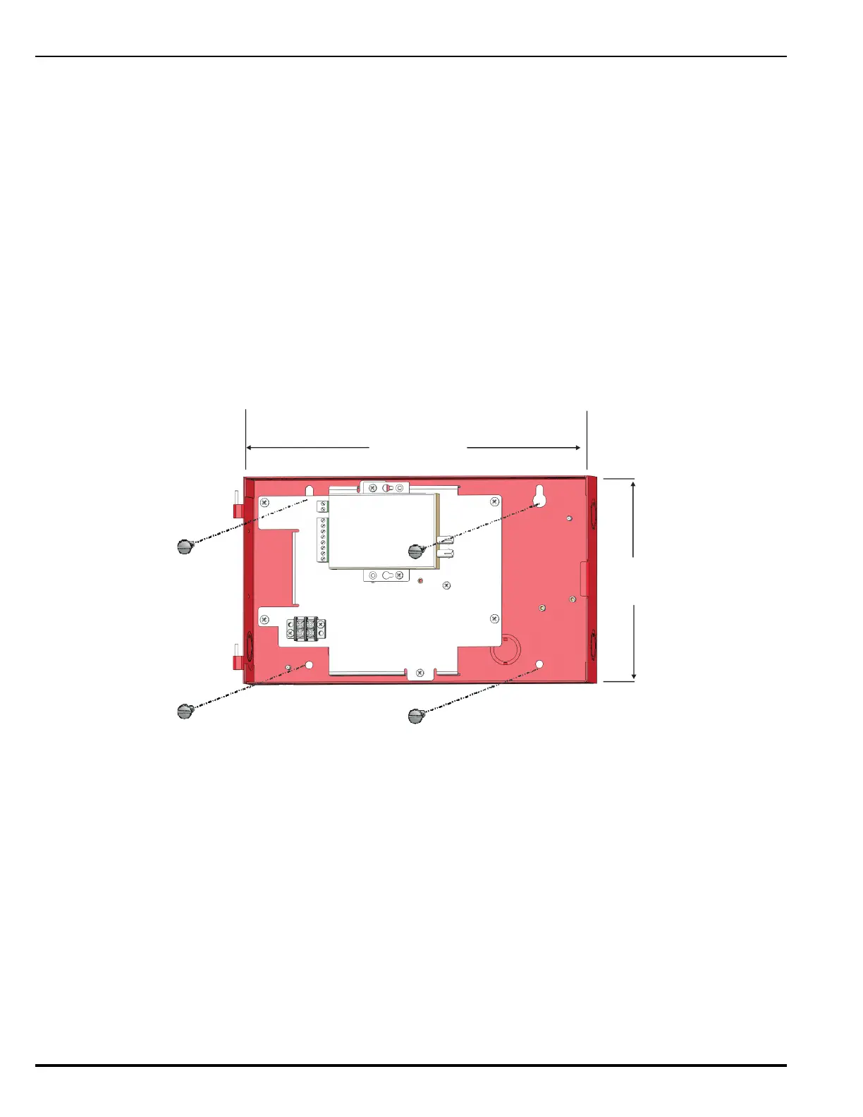
1. Mark and pre-drill holes for four mounting bolts using the dimensions shown. Two keyhole slots
(at the top) and two holes (at the bottom) serve as a template for surface mounting. Refer to
Figure 2-44 below.
Figure 2-44. Mounting the FOCM Enclosure
2. Insert the upper two fasteners into the wall. Leave approximately 1/4-inch of the screws
protruding.
3. Slip upper keyholes of the enclosure over the protruding screws. Tighten the screws.
4. Insert and tighten the two lower screws.
5. With the enclosure secured to the wall and power removed from the control unit, RS485, power
and duplex fiber-optic cables can be connected through the conduit knock-outs. Refer to the
wiring diagrams provided in Figure 2-45 (single channel) or Figure 2-46 (dual channel).
• Connect an RS485 data cable from the Network Interface Card terminal block J12 (for
Channel 1) or J13 (for Channel 2) to the RS485 input terminal block mounted inside the
enclosure. Refer to provided wiring diagrams in Figure 2-45 or Figure 2-46.
• Connect a 24 VDC power cable from the Power Management Unit (PMU) Board J9 AUX1 or
AUX2 terminal block outputs to the FOCM power input terminal block mounted inside the
enclosure.
7- in.
(190.5 mm)
½
13 in.
(330 mm)