General Information
February 2012 1-10 P/N 06-237058-001
1-9 MAIN CONTROLLER BOARD (MCB)
The ARIES NETLink’s main printed circuit board, P/N 76-800020-001, contains the system’s central
processing unit (CPU) and all of the primary circuits. The MCB is the heart of the system, controlling
the operation and supervision of all the system modules and software within the ARIES NETLink
system. It receives loop device data, processes the data based on pre-programmed instructions and
transmits output commands to the output modules, field devices and display(s).
The MCB is packaged separately inside the ARIES NETLink shipping carton. Refer to Chapter 2,
Section 2-4.7, for instructions on how to install the Main Controller Board.
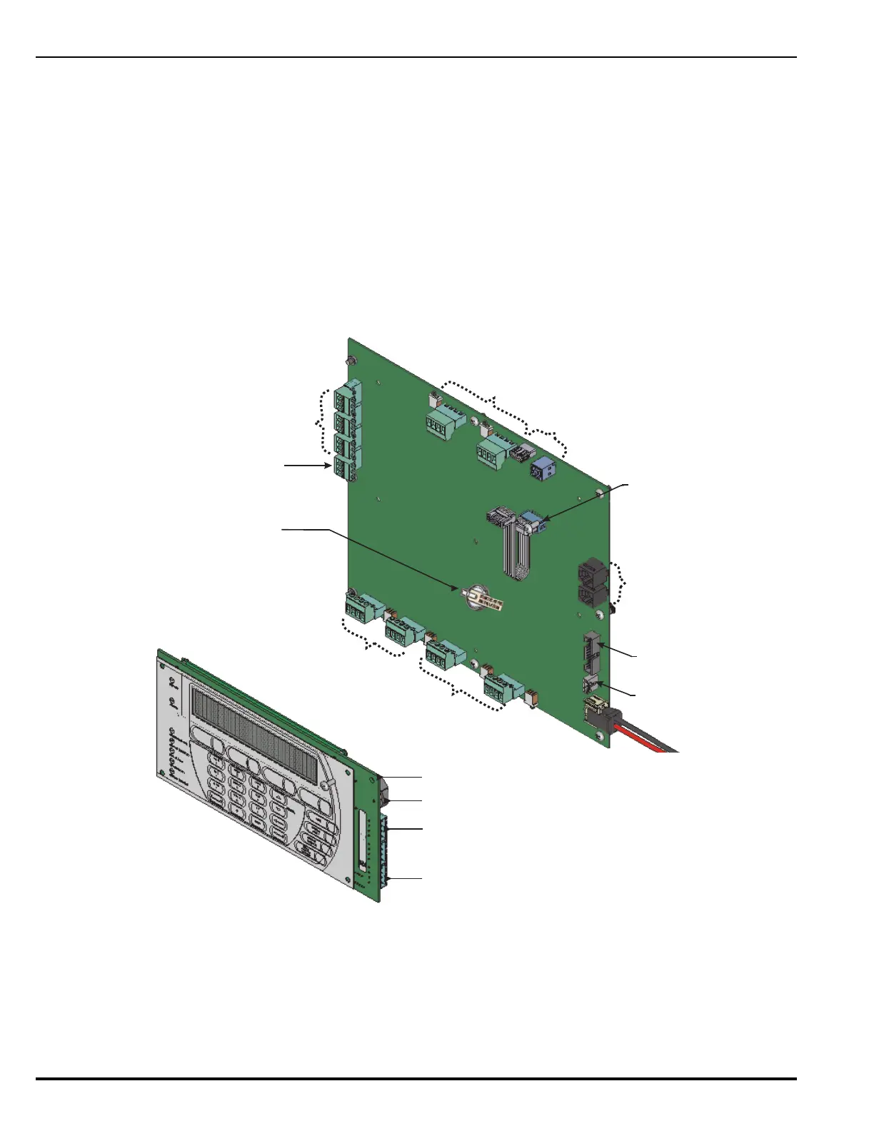
Figure 1-7 shows the layout of the MCB, including terminals for external components, the operator
interface, and connectors.
Figure 1-7. ARIES NETLink Main Controller Board Layout
RS485 to Integrated LED
Annunciator Module
Interface
RS485 Interface to Remote Display
Control Module and Remote LED
Annunciator Module
J8
J4
J6
Audible Buzzer
U
S
B
P
o
r
t
s
(
2
)
Communication to
Keypad/Display
RS232 Ports
Communication to
Card Cage Backplane
Communication to
PMU Board
J9
J2
J10
J12
RS232A
RS232B
J3
J8
Field-Configurable Relays (3)
Dedicated Trouble Relay
TB1
TB2
TB3
TB4
N
A
C
C
i
r
c
u
i
t
s
R
-
N
A
C
C
i
r
c
u
i
t
s
(
2
)
(
2
)
J
1
7
J
1
8
J
1
6
J
1
5
24 Vdc Power IN
from PMU Board
J
2
0
J
1
9
J
1
1
J
6
S
L
C
C
i
r
c
u
i
t
s
(
2
)
Real Time Clock Battery
(shown w/Battery Insulator Tab)
Trouble Sounder Connection
to PMU Board