Installation
February 2012 2-34 P/N 06-237058-001
2-8.6 Wiring Notification Appliance Circuits
The ARIES NETLink control unit has two on-board notification-appliance circuits (NACs) that are
labeled NAC1 and NAC2. These circuits have field-wiring connections that terminate at J16 and J15,
respectively. If more circuits are desired, an R-NAC Expansion Card offers three additional
R-NAC circuits (which can be used as NAC circuits). Each 24 Vdc regulated NAC circuit can supply
up to 1.5 A of current (for synchronizable devices) or 2.0A (for non-synchronizable devices) at a
nominal 24 Vdc for polarized notification appliances.
CLASS-A and CLASS-B wiring styles are shown below. When wiring for CLASS-A, resistors need to
be connected to a separate conductor to avoid placing two conductors inside a connector terminal.
A wire nut can be used to connect incoming field wiring to a resistor and connect lead wires to a
connector (as shown in the illustration below).
Note: For enclosures which include one or two power supply units, total current output of the
ARIES NETLink must not exceed 5.4 A per power supply unit. For enclosures which include
three or more power supply units, total current output must not exceed the parameters listed
in Appendix A, Section A-5, Calculating Maximum Load For Multiple Power Supply Units In
One Enclosure.
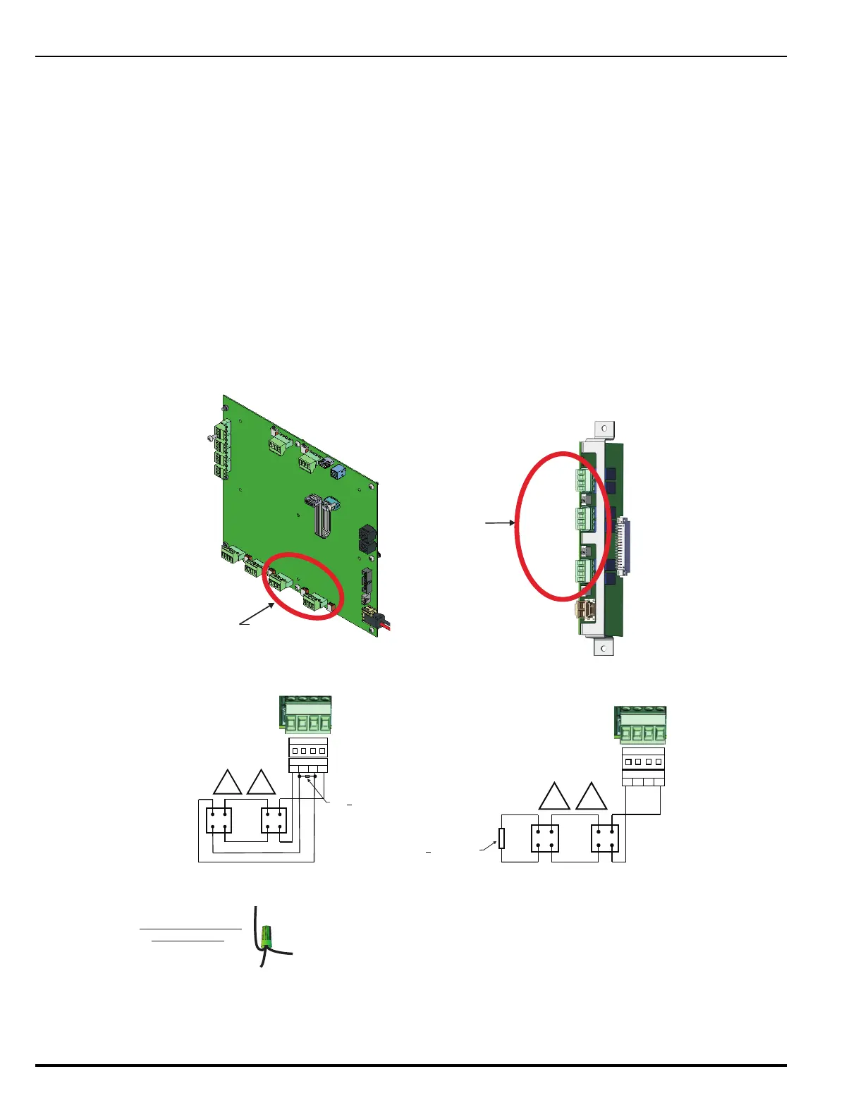
Figure 2-29. Wiring Diagram for Notification-Appliance Circuits
On-board NAC
Connectors
M
a
i
n
C
o
n
t
r
o
l
l
e
r
B
o
a
r
d
J
1
6
J
1
5
CLASS A Wiring
NOTIFICATION-APPLIANCE
CLASS B Wiring
NOTIFICATION-APPLIANCE
1. Suitable for synchronized and non-synchronized notification appliances.
Use polarized notification appliances only.
2. Maximum single notification-appliance current: 2.0 A for non-synchronized
devices, 1.5 A for synchronized devices.
3. Multiple conductors cannot be used on the terminal blocks. Multiple
conductors are to be connected as depicted at left.
Installation Notes:
Notification-Appliance Connectors
(located on MCB and R-NAC Expansion Card)
Expansion Card
R-NAC Connectors (3)
R-NAC 1
R-NAC 2
R-NAC 3
SP
-
+
-
+
End-of-Line Resistor,
10K +
5%, 0.5 W
R-NAC 1 or 2
IN+ IN-
OUT+ OUT-
SP
-
+
-
+
R-NAC 1 or 2
IN+ IN-
OUT+ OUT-
End-of-Line Resistor,
10K +
5%, 0.5 W
(Keep resistor as close to
connector as possible.)
To End-Of-Line
Resistor
To Device
To Terminal
TYPICAL WIRE NUT
CONNECTION