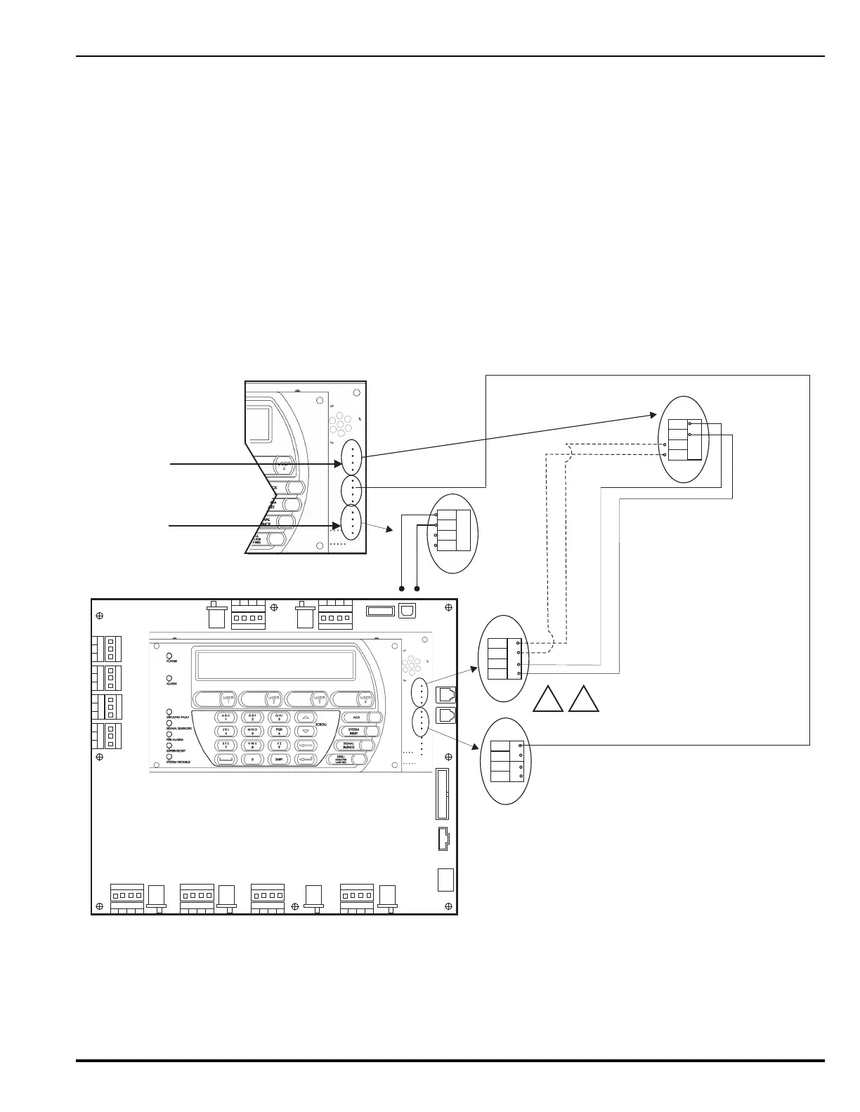
The RS485 communications circuit is power-limited. Figure 2-41 shows typical interconnections among the
channel.
Figure 2-41. RS485 Wiring Diagram for Remote Devices to MCB
TB1
RELAY 1
NO C
NC
TB2
RELAY 2
NO C
NC
TB3
RELAY 3
NO C
NC
TB3
TBL RELAY
NO
C
NC
J20 J19
SLC 2
IN+
OUT-
IN-
OUT+
USB HOST USB DEVICE
J17
R-NAC 1
IN+
OUT-
IN-
OUT+
NORMISOL
R-NAC 2
IN+
OUT-
IN-
OUT+
J18
NAC 1
IN+IN-
OUT+ OUT-
J16
ISOL NORM
ISOLNORM ISOLNORM
ISOL NORM
NAC 2
IN+IN-
OUT+ OUT-
J15
ISOL NORM
RS232 A
RS232 B
J10
24 VDC IN
J2
PMUCOMMS
OUT
J9
BACKPLANE
COMMSOUT
RS485
IN-B
IN-A
OUT-A
OUT-B
Main Controller Board
(MCB)
SLC 1
IN+
OUT-
IN-
OUT+
RS485
IN-B
IN-A
OUT-A
OUT-B
S P
24 VDC PWR
IN-
IN+
OUT+
OUT-
Communications Circuit
(
J8
)
Voltage:
24 VDC
Current: Per RS485 Standard
Recommended Wire: Twisted, shielded,
low-capacitance, fire-alarm wire
Max. Wire Length: 4,000 Ft. per twisted pair
Use the following remote control modules only
:
Module Type Model No.
Display / Control RDCM
Display R-LAM
J8
J8
J4
J8
J
8
J4
RDCM
Installation Notes:
RS485 circuits must be terminated at the first and last device in the circuit.
First device is the main Keypad/Display with termination resistor SW2
(located on the back side of the board) set to the ON (terminated) position.
For Remote Keypad/Display and RDCM boards, set termination resistor SW2
to the OFF (open) position for intermediate assemblies by moving the small
white switch lever. Leave in the ON position if assembly is the last device in
the circuit. For ATM-L or ATM-R assembly termination settings, refer to the
Model ATM-L/R Series Drivers Installation Manual, P/N 06-236179-002.
For remote synchronization between RDCMs, R-LAMs and the control unit
(having power supply connections common to all), install wire from
LED SYNCH OUT+ of the originating device to LED SYNCH OUT- of the first
remote peripheral device. Continue for as many remote devices in the system.
Note: An R-LAM cannot be an originating device.
For Dual Channel Installation
On the R-LAM, the location of these
2 connectors is reversed; i.e., its J6
(PWR IN) 24 Vdc connector is at
the top, and its J8 (RS485) bus
connector is at the bottom.
J6
1.
2.
+
-
J6
OUT+
OUT-
LED SYNCH
PSU TBL
J6