Installation
February 2012 2-38 P/N 06-237058-001
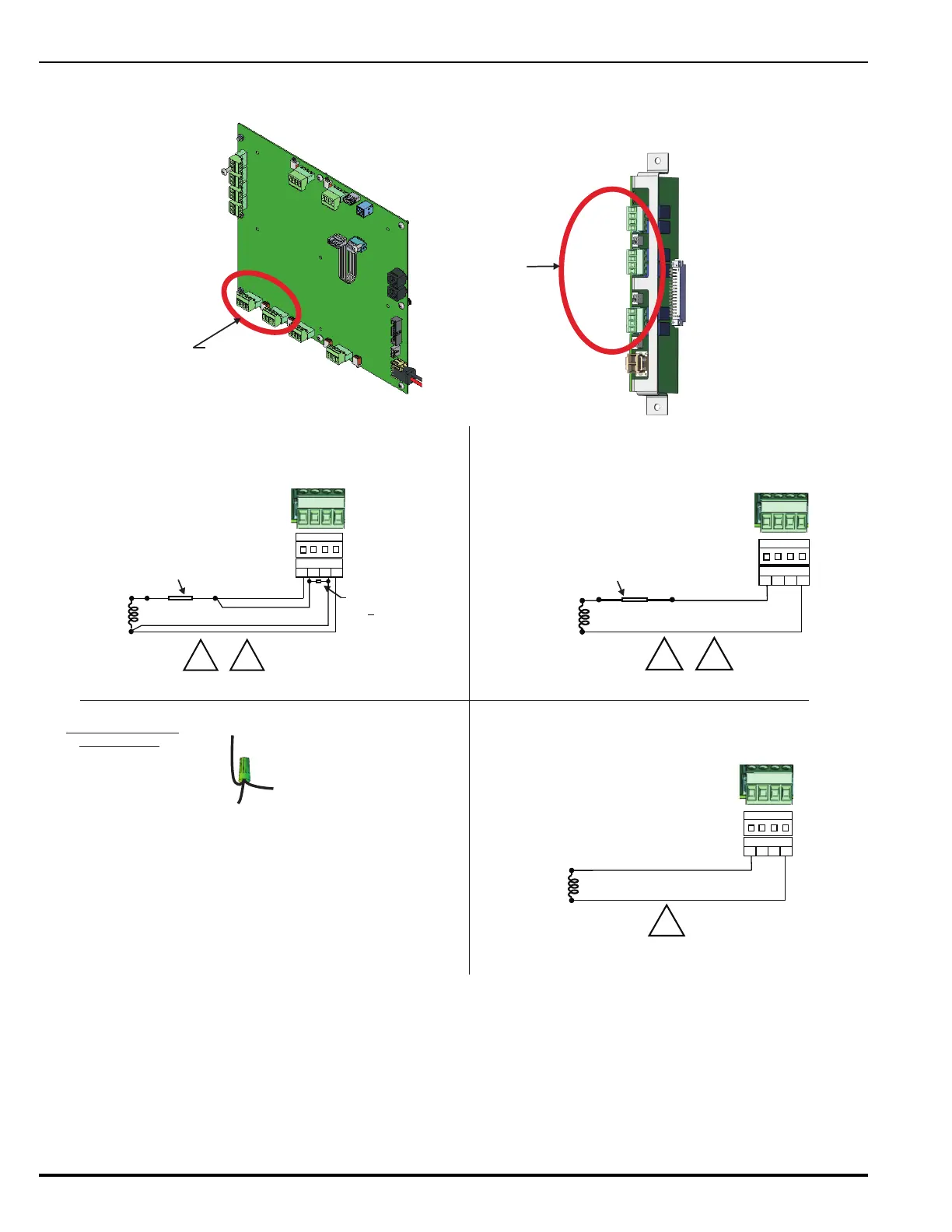
Figure 2-31. Wiring Diagrams for Solenoid-Based Releasing Devices
On-board R-NAC
Connectors
M
a
i
n
C
o
n
t
r
o
l
l
e
r
B
o
a
r
d
J
1
7
J
1
8
Expansion Card
R-NAC Connectors (3)
R-NAC 1
R-NAC 2
R-NAC 3
Release Notification-Appliance Connectors
(located on MCB and R-NAC Expansion Card)
Release Circuits - Solenoid
CLASS A, Power-Limited Wiring
Release Circuits - Solenoid
CLASS B, Power-Limited Wiring
Release Circuits - Solenoid
CLASS B, Non-Power-Limited
S
(Non-Power-Limited when In-Line Device not used)
R-NAC 1 or 2
IN+ IN-
OUT+ OUT-
RedBlk
S P
In-Line Releasing Device, P/N 06-220023-001
(Must be close nippled to solenoid enclosure)
R-NAC 1 or 2
IN+ IN-
OUT+ OUT-
Red
Blk
n-Line Releasing Device, P/N 76-800000-004
(Must be close nippled to solenoid enclosure)
R-NAC 1 or 2
IN+ IN-
OUT+ OUT-
End-of-Line Resistor,
10K +
5%, 0.5 W
S P
(Keep resistor as close to
connector as possible.)
2. Route non-power-limited wiring at least ¼-in. away from
all power-limited wiring. Place non-power-limited wiring
inside a conduit.
1. Refer to Table C-2 in Appendix C of this manual for nominal
resistance for a specific solenoid-based device.
3. Multiple conductors cannot be used on the terminal blocks.
Multiple conductors are to be connected as depicted above.
To End-Of-Line
Resistor
To Device
To Terminal
TYPICAL WIRE NUT
CONNECTION