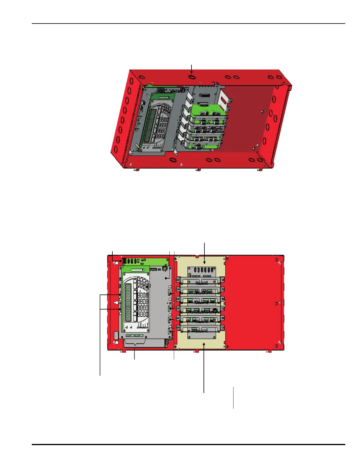
Figure E-2. Example Showing Wiring in 3-Tiered Enclosure with Card Cage Assembly (a); Location of knockouts (b)
Maintain 1/4-in. separation between power-limited
and non-power-limited wiring. Place non-power-
limited wiring inside a conduit.
(a)
AC Mains In: Non-Power Limited
SLC Circuits:
Power-Limited
R-NAC 1
R-NAC 2
NAC 1
NAC 2
R-NAC 1 & R-NAC 2:
(If Non-Power-Limited
option is used.)
NAC 1 & NAC 2: Power Limited
Also
R-NAC 1 & R-NAC 2:
(If Power-Limited option is used.)
AUX 1 & AUX 2: Power Limited
Voltage-Free Relays:
Non-Power-Limited
NOTE:
Route Power-Limited
wiring from RIGHT side
of enclosure.
NOTE:
Route Non-Power-Limited
wiring from LEFT side of
the enclosure (Relays,
R-NAC’s, City Tie-Shunt
Type).
: If Non-Power-
Limited wiring is not
being used, Power-
Limited Wiring can be
routed on LEFT side of
the enclosure.
Exception
SLC Card
Relay Card
R-NAC Card
City Tie Card
Run wires through knockouts as shown to keep
power-limited and non-power-limited outputs separate.
Keep AC Power wiring from PMU
to PMU dressed snug against
back of enclosure.
(b)
Knockout