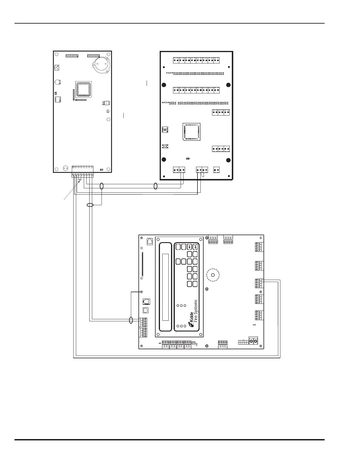
Figure 2-27. Single-Channel RS-485 Wiring to Peripheral Devices
1
2
3
4
5
6
7
8
W2
SW2
DS1
JK1
JK2
SW1
W1
TB1
VR1
VR2
16
15
14
13
12
11
10
9
8
7
6
5
4
3
2
1
Lamp Test
Com
Ack
Reset
Silence
Drill
32
31
30
29
28
27
26
25
24
23
22
21
20
19
18
17
LK19
LK21
LK18
LK20
LK23
LK22
LK25 LK24
LK27 LK26
LK29 LK28
LK31 LK30
LK32
LK17
LK15LK16
LK13LK14
LK11LK12
LK10
LK8
LK6
LK4
LK2
LK9
LK7
LK5
LK3
LK1
Trouble
Sup.
Sil. Out
Pre Alm
Alarm
Pwr On
A
B
+24 V
Com
PS Flt
W1
Out B
Out A
In B
In A
S2 S1
ATM-L
Remove W2
Install W1
AC POWER
ALARM
PRE-ALARM
SYSTEM TROUBLE
SUPERVISORY
SILENCE
SYSTEM
ACKNOWLEDGE
SYSTEM
RESET
SILENCE
SCROLL
12345
67890
Combo 2
TB6TB7
Combo 1
TB2
Aux 24 VDC
TB11
Release 2
TB12
Release 1
Batt Out
TB3
TroubleRelay 3
Relay 1
Relay 2
1234 1234
1234
1234 1234
120
240
TB13
AC IN
NL
PSU
J12
+
+
--CNCNO
CNCNO
CNCNOCNCNO
SLC
1234
TB5
NAC 1
TB14
1234
NAC 2
RS-232 A
J8
J5
J3
J6
TB15
USB A
USB B
RS 485SLC
TB1
4321
4321
Style 4
S2
J10
Maximum Length: 4,000 Ft.
(Twisted, Shielded, Low-Capacitance Wire)
Refer to Figure 2-29 for maximum-length estimation.
Note: All wiring is power-limited and supervised.
J3
RS-232 B
RDCM Circuit Board
Install Jumper
Connect wire for shield to earth-ground
screw in upper-edge of PCB.
Connect wires for shields together at each
intermediate remote annunciator. Do not connect
wires for shields to the earth-ground screw in
remote enclosures.
Leave shield wire floating at last remote annunciator. Do not
connect wire for shield to the earth-ground screw in last
remote enclosure. Trim shield wire as much as possible.