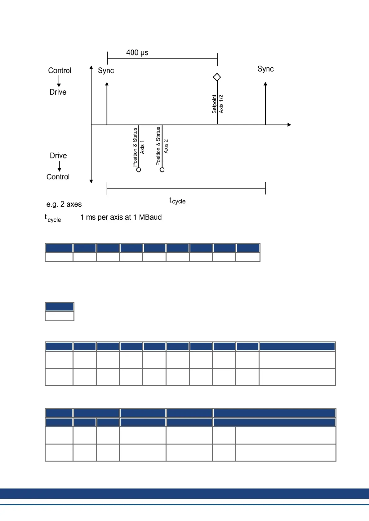
The configuration above now enables a cyclical sequence, as shown in the diagram:
RPDO 2 can now be used to supply trajectory data for both axes, e.g.:
COB-ID Byte 0 Byte 1 Byte 2 Byte 3 Byte 4 Byte 5 Byte 6 Byte 7
301 F4 01 00 00 E8 03 00 00
In this example, the first axis receives a trajectory value of 500 increments (Bytes 0 to 3) and the second axis
receives a trajectory value of 1000 increments.
The axes accept these values, and the positioning is made when the next SYNC telegram is received.
SYNC telegram
COB-ID
080
Afterwards, both axes send back their incremental positions and the contents of their status registers when the
SYNC Object with the COB-ID for the 2
nd
TPDO is received.
COB-ID Byte 0 Byte 1 Byte 2 Byte 3 Byte 4 Byte 5 Byte 6 Byte 7 Comment
181 23 01 00 00 00 00 03 44 position + manufacturer
status register for axis1
182 A5 02 00 00 00 00 03 44 position + manufacturer
status register for axis2
If an error occurs during operation, the axis transmits an Emergency message, which could appear like this:
Emergency Object
COB-ID Emergency error Error register Category
Low High
081 10 43 08 01 00 00
00 00
motor temperature, temperature,
manufacturer-specific
081 00 00 08 00 00 00
00 00
AKD CANopen | 8 Appendix
Kollmorgen™ | November 2012 155