AKD CANopen | 4 Installation and Setup
4.2.3 Node Address for CAN-Bus
After changing the node address, you must turn off the 24 V auxiliary supply
for the drive and then turn it on again.
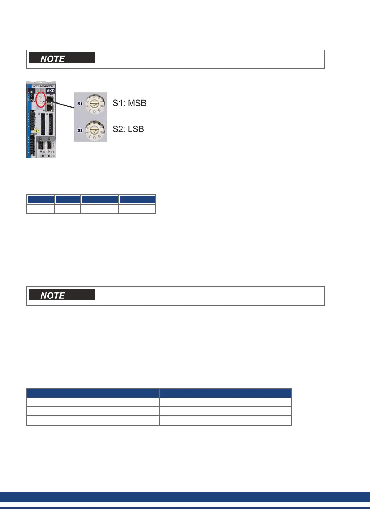
During setup, use the rotary switches on the AKD front panel to preset the station address for communication.
The rotary switches on the front of the AKD (S1&S2) correspond to the CAN node address.
The S1&S2 switches also correspond to the IP address setting of the drive. Both CAN and IP network address
schemes have to be configured to account for this dependence if both TCP/IP and CAN networks are running at
the same time in an application. Example:
S1 (MSB) S2 (LSB) CAN address IP address
4 5 45 192.168.0.45
The IP address setting can be decoupled from the Rotary switches using settings in the drive. Use Settings ->
Fieldbus-> TCP/IP to adjust these settings.
4.2.4 CAN-Bus Termination
The last bus device on both ends of the CAN-Bus system must have termination resistors. The AKD has built-in
132 ohms resistors that can be activated by connecting pins 1 and 6. An optional termination plug is available for
AKD (P-AKD-CAN-TERM). The optional termination plug is an RJ-12 connector with an enclosed wire jumper
between pins 1&6. A plug should be inserted into the X13 connector of the last drive in the CAN network.
Remove the termination connector if the AKD is not the last CAN-Bus device
and use X13 for connecting the next CAN node.
4.2.5 CAN-Bus Cable
To meet ISO 11898, a bus cable with a characteristic impedance of 120 ohms should be used. The maximum
usable cable length for reliable communication decreases with increasing transmission speed. As a guide, you
can use the following values which Kollmorgen™ has measured; however, these values are not assured limits:
l Characteristic impedance: 100–120 ohms
l Cable capacitance max.: 60 nF/km
l Lead loop resistance: 159.8 ohms/km
Cable length, depending on the transmission rate:
Transmission Rate (kBaud) Maximum Cable Length (m)
1,000 10
500 70
250 115
Lower cable capacitance (max. 30 nF/km) and lower lead resistance (loop resistance, 115 ohms/1000m) make it
possible to achieve greater distances.
(Characteristic impedance 150 ± 5 ohms requires terminating resistor 150 ± 5 ohms).
20 Kollmorgen™ | November 2012