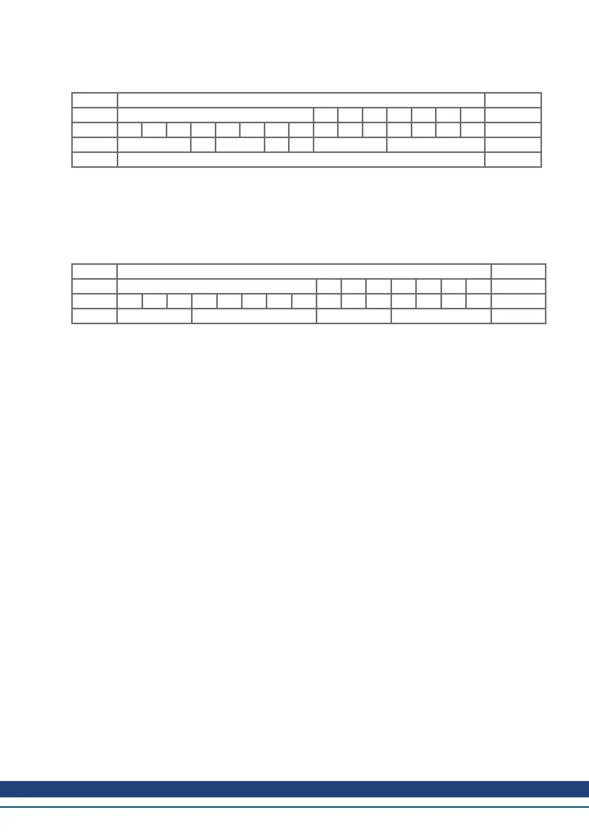
To write data, the control byte must be written in the manner shown below:
Client Initiate Domain Download Server
Byte 1 2 3 4 5 6 7 8
request 7 6 5 4 3 2 1 0 indication
=> ccs=1 X n e s m d =>
=> => => => => =>=> => =>=> => =>=> => =>=> => =>=> => =>
n,e and s are defined like in the reading case, m: index + Subindex, d: 4 bytes data field
The data length of an object can be taken from the object dictionary in the appendix.
The control byte should be:
0x23 for a 4-byte access
0x27 for a 3-byte access
0x2B for a 2-byte access
0x2F for a 1-byte access
Client <= <= <= <= <= <=<= <= <=<= <= <=<= <= <=<= <= <=<= <= <= Server
Byte 1 2 3 4 5 6 7 8
confirm 7 6 5 4 3 2 1 0 response
<= scs=3 X min reserved <=
2. Index (Bytes 2 and 3):
The Index is the main entry in the Object Dictionary, and divides the parameters into groups.
(Example: Index 1018h is the Identity Object). As for all CAN data, the Index is stored with the bytes in reverse
order.
For example: Index 6040h means Byte 2 = 40h, Byte 3 = 60h)
3. Subindex (Byte 4):
The Subindex divides the parameters within a group of parameters.
4. Data field (Bytes 5 to 8):
These components are used for the exchange of user data. In read-request telegrams to the AKD they are set to
0. They have no content in a write confirmation from the AKD if the transfer was successful, but if the write oper-
ation was faulty they contain an error => p. 42.
AKD CANopen | 6 CANopen Communication Profile
Kollmorgen™ | November 2012 35