Filter keyboard tracking
Tracking Low/High
These settings specify keyboard tracking for the cutoff fre-
quency of the filter for the selected oscillator. The way in
which the cutoff frequency is affected by the keyboard loca-
tion you play can be specified by the “Tracking Low”, “Track-
ing High”, “Ramp Low” and “Ramp High” parameters.
C–1…G9 Lowest/Highest note in the range.
Tracking Low
Keyboard tracking will apply to the range below the specified
note number.
Tracking High
Keyboard tracking will apply to the range above the specified
note number.
Ramp
This parameter specifies the angle of keyboard tracking.
-99…+99 Angle value.
Here is how cutoff frequency is affected by keyboard location
and the Ramp setting (“Intensity to A” and “Intensity to B” =
+50):
Ramp Low
Ramp High
If “Intensity to A” and “Intensity to B” are set to +50, “Ramp
Low” is set to –62 and “Ramp High” is set to +62, the angle of
the change in cutoff frequency will correspond to the key-
board location (pitch). This means that the oscillation that
occurs when you increase the “Resonance A” will correspond
to the keyboard location.
If you set “Ramp Low” to +43 and “Ramp High” to –43, the
cutoff frequency will not be affected by keyboard location.
Use this setting when you do not want the cutoff frequency to
change for each note.
Tracking to A/B
These parameters specify the note numbers at which key-
board tracking will begin to apply, and set the “Intensity to A”
and “Intensity to B” parameters to specify the depth and
direction of the change applied to filters A and B.
For the range of notes between “Key Low” and “Key High”,
the cutoff frequency will change according to the keyboard
location (pitch).
-99…+99 Parameter value.
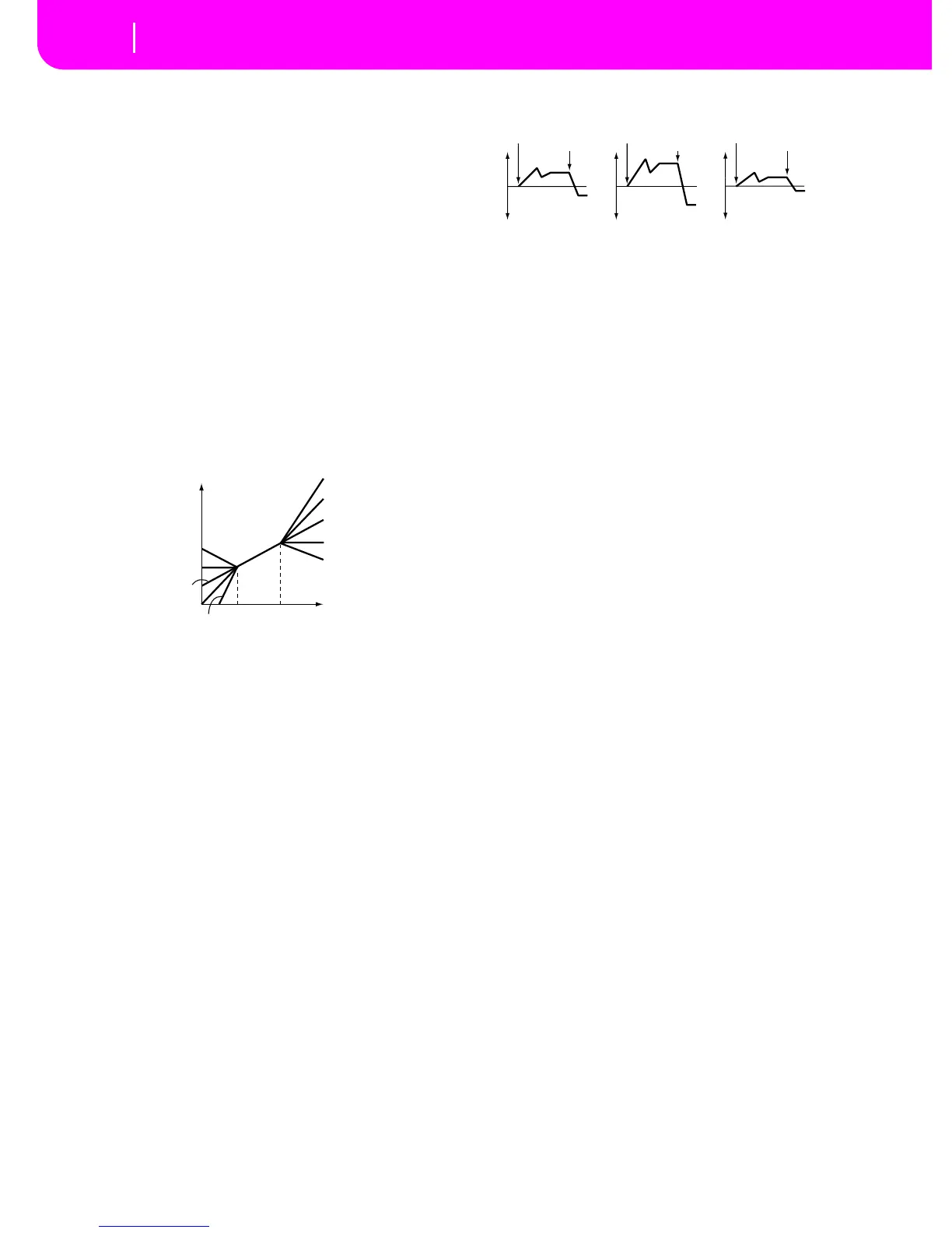
Filter EG modulation
Velocity to A
This parameter specifies the depth and direction of the effect
that velocity will have on the time-varying changes created by
the filter EG (as set on “Page 11 - Filter EG”) to control the
filter A cutoff frequency.
With positive (+) values, playing more strongly will cause the
filter EG to produce greater changes in cutoff frequency. With
negative (–) values, playing more strongly will also cause the
filter EG to produce greater changes in cutoff frequency, but
with the polarity of the EG inverted.
99…+99 Value of the Velocity to A parameter.
Velocity to B
This parameter specifies the depth and direction of the effect
that velocity will have on the time-varying changes created by
the filter EG to control the filter B cutoff frequency (see
“Velocity to A”).
99…+99 Value of the Velocity to B parameter.
EG Intensity to A
Specifies the depth and direction of the effect that the time-
varying changes created by the filter 1 EG will have on the fil-
ter A cutoff frequency.
With positive (+) settings, the sound will become brighter
when the EG levels set by Filter EG “Level” and “Time”
parameters are in the “+” area, and darker when they are in
the “–” area.
With negative (–) settings, the sound will become darker
when the EG levels set by Filter EG “Level” and “Time”
parameters are in the “+” area, and brighter when they are in
the “–” area.
-99…+99 Parameter value.
EG Intensity to B
Specifies the depth and direction of the effect that the time-
varying changes created by the filter EG will have on the filter
B cutoff frequency (see “EG Intensity to A”).
-99…+99 Parameter value.
EG AMS (Alternate Modulation Source)
Selects the source that will control the depth and direction of
the effect that the time-varying changes produced by the fil-
ter EG will have on the cutoff frequency of filters A and B. See
“AMS (Alternate Modulation Source) list” on page 14-19.
Intensity to A
Specifies the depth and direction of the effect that “AMS” will
have on filter A. For details on how this will apply, refer to
“EG Intensity to A”.
Intensity to B
Specifies the depth and direction of the effect that “AMS” will
have on filter B. For details on how this will apply, refer to
“EG Intensity to A”.
Cutoff frequency
Key
Low Ramp=+99
Low Ramp=+43
Low Ramp=0
Low Ramp=–62
Low Ramp=–99
High Ramp=+99
High Ramp=+62
High Ramp=0
High Ramp=–43
High Ramp=–99
Low Key
High Key
Changes in cutoff frequency
Softly played Strongly played
Setting to –
Strongly played
Setting to +
Note-on
Note-off
Note-on
Note-off
Note-on
Note-off
 Loading...