Start Level Swing
This parameter specifies the direction in which “AMS” will
change “Start Level”. If “Intensity” is set to a positive (+)
value, setting this parameter to + will allow AMS to increase
the EG level, and setting this parameter to – will allow AMS
to decrease the EG level. With a setting of 0, no change will
occur.
Attack Level Swing
This parameter specifies the direction in which “AMS” will
change “Attack Level”. If “Intensity” is set to a positive (+)
value, setting this parameter to + will allow AMS to increase
the EG level, and setting this parameter to – will allow AMS
to decrease the EG level. With a setting of 0, no change will
occur.
Break Point Level Swing
This parameter specifies the direction in which “AMS” will
change “Break Level”. If “Intensity” is set to a positive (+)
value, setting this parameter to + will allow AMS to increase
the EG level, and setting this parameter to – will allow AMS
to decrease the EG level. With a setting of 0, no change will
occur.
Amp EG ‘Time’ modulation
These parameters let you use an alternate modulation source
to modify the amp EG times that were specified in “Attack/
Decay/Slope/Release Time” on page 14-15.
AMS1(T) (Alternate Modulation Source 1 - Time)
This parameter specifies the source that will control the
“Time” parameters of the amp EG (see “AMS (Alternate
Modulation Source) list” on page 14-19). With a setting of
Off, there will be no modulation.
Intensity
This parameter specifies the depth and direction of the effect
that “AMS1” will have. For example, if “AMS1(T)” is Amp
KTrk +/+, the (Amp) Keyboard Track settings (see “Amplifier
keyboard tracking” on page 14-14) will control the EG
“Time” parameters. With positive (+) values of this parame-
ter, positive (+) values of “Ramp (Ramp Setting) will cause
EG times to be lengthened, and negative (–) values of “Ramp
(Ramp Setting)” will cause EG times to be shortened. The
direction of the change is specified by “Attack Time Swing”,
“Decay Time Swing”, “Slope Time Swing”, and “Release
Time”.
When “AMS1(T)” is Velocity, positive (+) values will cause
EG times to lengthen as you play more strongly, and negative
(–) values will cause EG times to shorten as you play more
strongly. With a setting of 0, the EG times will be as specified
by the “Amp envelope” parameters (see page 14-15).
Attack Time Swing
This parameter specifies the direction of the effect that
“AMS1” will have on “Attack Time”. With positive (+) values
of “Intensity”, setting this parameter to + will allow AMS1 to
lengthen the time, and setting it to – will allow AMS1 to
shorten the time. With a setting of 0 there will be no effect.
Decay Time Swing
This parameter specifies the direction of the effect that
“AMS1” will have on “Decay Time”. With positive (+) values
of “Intensity”, setting this parameter to + will allow AMS1 to
lengthen the time, and setting it to – will allow AMS1 to
shorten the time. With a setting of 0 there will be no effect.
Slope Time Swing
This parameter specifies the direction of the effect that
“AMS1” will have on “Slope Time”. With positive (+) values
of “Intensity”, setting this parameter to + will allow AMS1 to
lengthen the time, and setting it to – will allow AMS1 to
shorten the time. With a setting of 0 there will be no effect.
Release Time
This parameter specifies the direction of the effect that
“AMS1” will have on “Release Time”. With positive (+) val-
ues of “Intensity”, setting this parameter to + will allow AMS1
to lengthen the time, and setting it to – will allow AMS1 to
shorten the time. With a setting of 0 there will be no effect.
AMS2 (Alternate Modulation Source 2)
This is another alternate modulation source for the Amp EG.
See above “AMS1” parameters.
PAGE 17 - LFO1
In this and the next page you can make settings for the LFO
that can be used to cyclically modulate the Pitch, Filter, and
Amp of each oscillator. There are two LFO units for each
oscillator. By setting the LFO1 or LFO2 Intensity to a negative
(–) value for Pitch, Filter, or Amp, you can invert the LFO
waveform.
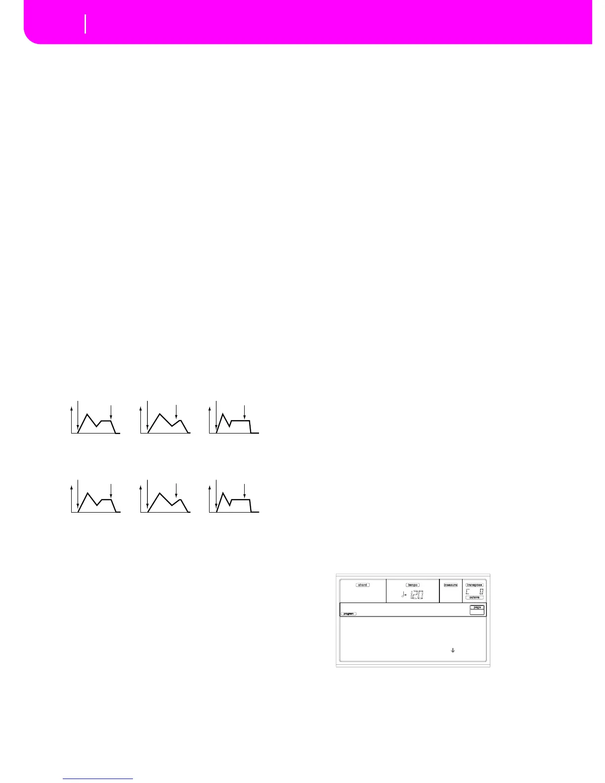
Amp 1 EG changes (Time) (AMS=Velocity, Intensity= a positive (+) value)
Amp 1 EG changes (Time)
(AMS=Amp KTrk +/+, Intensity = a positive (+) value)
(When Amp Keyboard Track “Low Ramp”= a positive (+) value, and
“High Ramp” = a positive (+) value)
Note-on
Note-off
Note-on
Note-off
Note-on
Note-off
Note-on
Note-off
Note-on
Note-off
Note-on
Note-off
Low-pitched note played with
Attack, Decay, Slope, and
Release Time Swing at +
Softly played note with
Attack, Decay, Slope and
Release Time Swing at +
High -pitched note played with
Attack, Decay, Slope, and
Release Time Swing at –
Strongly played note with
Attack, Decay, Slope and
Release Time Swing at +
Strongly played note with
Attack, Decay, Slope and
Release Time Swing at –
Selected: Osc1
Wave: Triangle Rand
Frequency: 31
Key Sync: On
LFO1 |Osc1