2J0/2J1/2J2
1-5-15
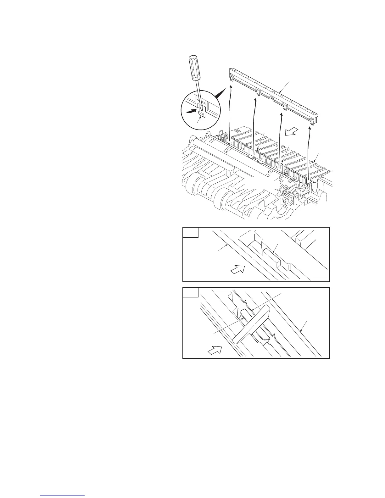
6. Release four latches and then remove the
separation charger brush unit.
7. Check or replace the transfer roller and sep-
aration charger brush unit and refit all the
removed parts.
CAUTION: Note the following, when refitting
the separation charger brush unit.
A. The separation charger brush unit is
inserted into the two projections of the frame
and does not run on to the projections.
B. The separation charger brush unit is
firmly in contact with the separation charger
plate of the frame.
Figure 1-5-19
Separation charger
brush unit
Frame
Latch
Separation
charger plate
Projection
Projection
A
B
Separation
charger plate
Separation
charger brush
Separation
charger brush unit
Separation charger
brush unit
Projection
Viewpoint
Viewpoint
Viewpoint

 Loading...