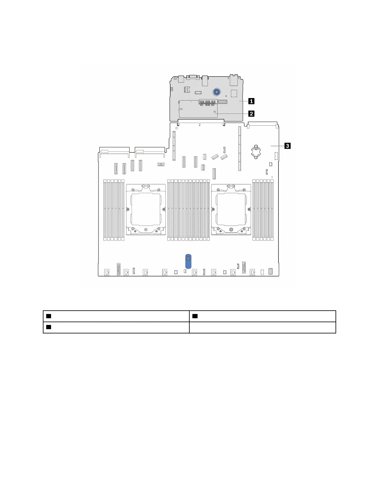
The following illustration shows the layout of the system board (system board assembly) which contains the
system I/O board and processor board.
Figure 101. System-board-assembly layout
1 System I/O board
3 Processor board
2 Firmware and RoT security module
•
“Remove the firmware and RoT security module” on page 135
• “Install the firmware and RoT security module” on page 137
• “Remove the system I/O board or processor board” on page 141
• “Install the system I/O board or processor board” on page 145
Remove the firmware and RoT security module
Follow instructions in this section to remove the ThinkSystem V3 Firmware and Root of Trust Security
Module (firmware and RoT security module).
About this task
Chapter 5. Hardware replacement procedures 135

 Loading...


