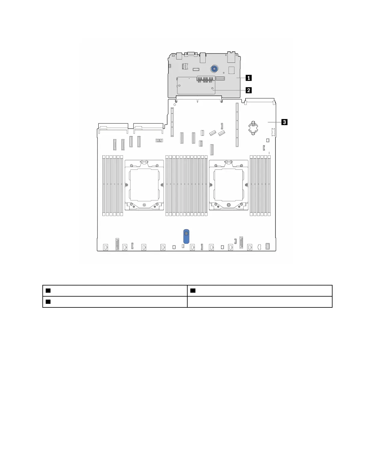
Figure 10. System-board-assembly layout
1 System I/O board
3 Processor board
2 Firmware and RoT security module
For more information about the connectors, switches, or LEDs that are available on the system board
(system board assembly), see:
•
“System-board-assembly connectors” on page 21
• “System-board-assembly switches” on page 23
• “System-board-assembly LEDs” on page 196
System-board-assembly connectors
The following illustrations show the internal connectors on the system board (system board assembly).
Chapter 2. Server components 21

 Loading...


