a. Gently open the retaining clip on each end of the memory module slots next to the left and
right sides of the processor.
b.
Grasp the processor filler with both hands and carefully lift it out of the slots.
Step 2. (Optional) Remove the processor socket cover.
The procedure of removing the processor socket cover is the same as that of removing a
processor. See
“Remove a processor” on page 110.
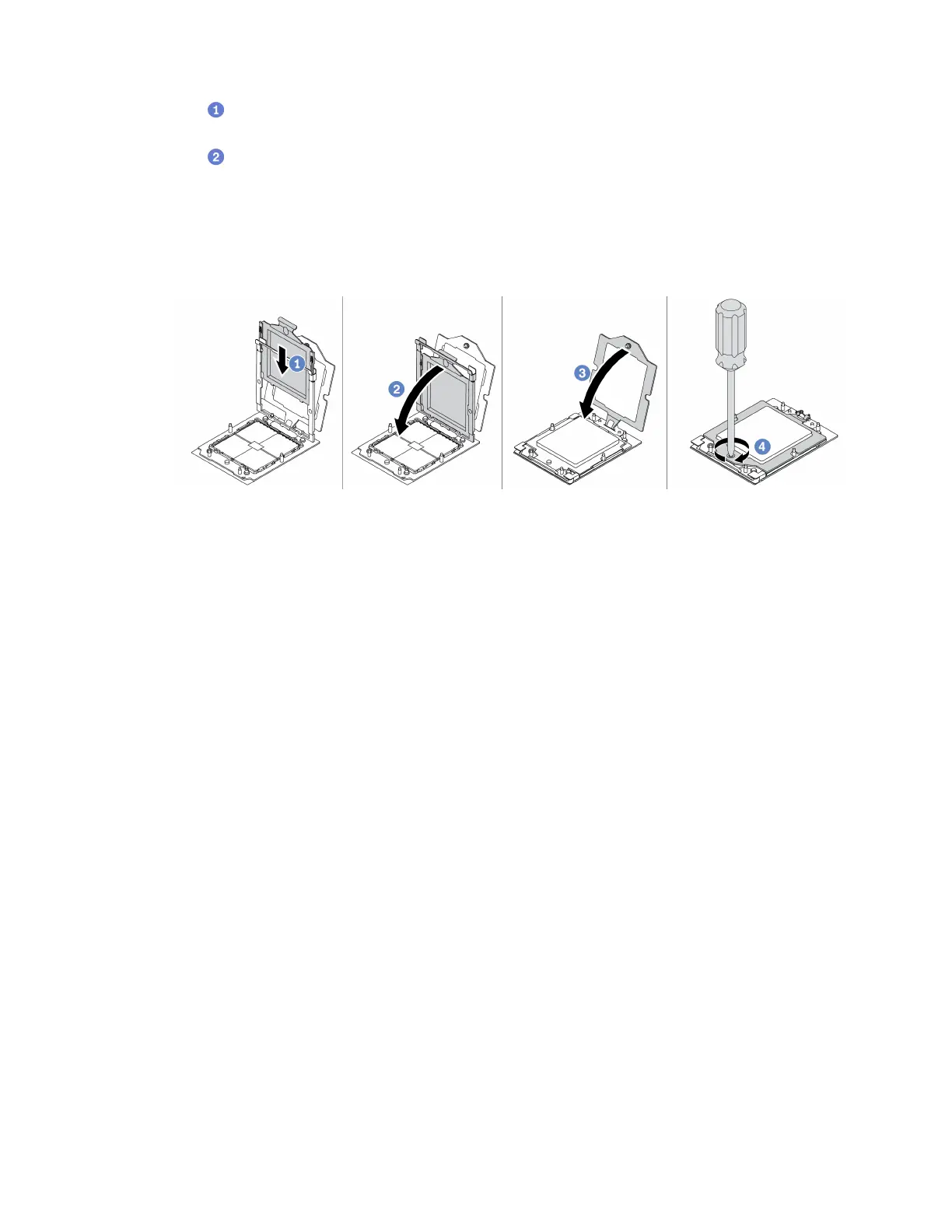
Step 3. Install the processor.
Figure 74. Installing a processor
Step 4. Slide the processor carrier into the rail frame.
Step 5. Push the rail frame down until the blue latches lock into place.
Step 6. Close the retention frame.
Step 7. Use a Torx T20 screwdriver to tighten the captive screw.
After you finish
Install the heat sink. See
“Install a heat sink” on page 113.
Install a heat sink
Follow the instructions in this section to install a heat sink. This task requires a Torx T20 screwdriver. The
procedure must be executed by a trained technician.
About this task
Important: This task must be operated by trained technicians that are certified by Lenovo Service. Do no
attempt to remove or install it without proper training and qualification.
Attention:
• Read
“Installation Guidelines” on page 35 and “Safety inspection checklist” on page 36 to ensure that you
work safely.
• Power off the server and peripheral devices and disconnect the power cords and all external cables. See
“Power off the server” on page 44.
• Prevent exposure to static electricity, which might lead to system halt and loss of data, by keeping static-
sensitive components in their static-protective packages until installation, and handling these devices with
an electrostatic-discharge wrist strap or other grounding system.
Procedure
Chapter 5. Hardware replacement procedures 113

 Loading...


