Step 1. Touch the static-protective package that contains the backplane to any unpainted surface on the
outside of the server. And then, take the backplane out of the package and place it on a static-
protective surface.
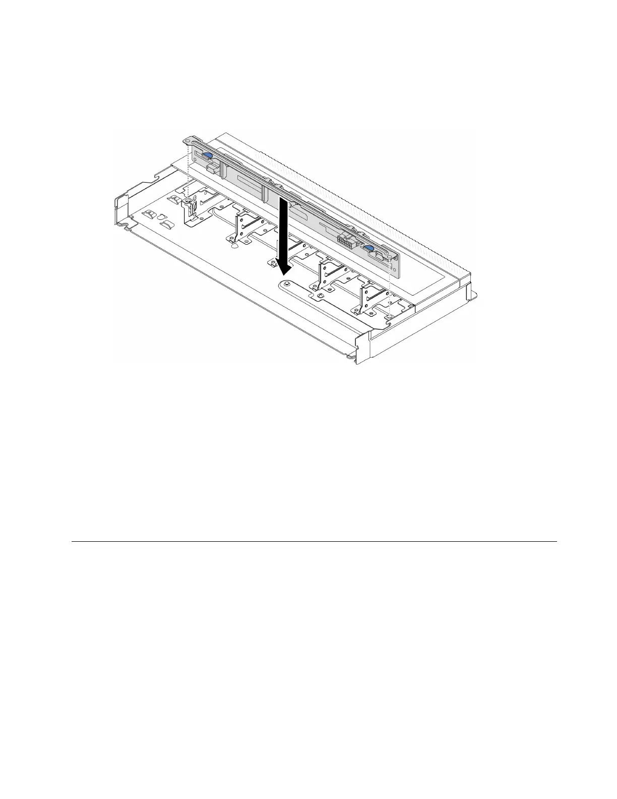
Step 2. Align the two pins on the backplane with the corresponding holes in the chassis.
Figure 30. Installation of backplane for ten 2.5-inch hot-swap drives
Step 3. Lower the backplane into the chassis. Ensure that the pins pass through the holes and the
backplane is fully seated in place.
Step 4. Connect the cables to the backplane. See
Chapter 6 “Internal cable routing” on page 157. If the
cable connectors come with protective dust caps, make sure to remove them before plugging in.
After you finish
1. Reinstall all the drives and drive fillers into the drive bays. See
“Install a 2.5/3.5-inch hot-swap drive” on
page 69
.
2. Complete the parts replacement. See “Complete the parts replacement” on page 154.
Front I/O module replacement
Use this information to remove and install the front I/O module.
•
“Remove the front I/O module” on page 61
• “Install the front I/O module” on page 62
Remove the front I/O module
Use this information to remove the front I/O module.
About this task
The following illustrates how to remove the front I/O module with front operator panel. You can remove other
front I/O modules in the same way.
Chapter 5. Hardware replacement procedures 61

 Loading...


