CFF RAID adapter
Use the section to understand the power cable and signal input cable routing for CFF RAID adapters.
Cable routing for CFF RAID adapters
• For the locations of connectors on CFF RAID adapters and the processor board, see
“System-board-
assembly connectors” on page 21
for details.
• For more information about the CFF RAID adapters supported, see
“Technical specifications” on page 3
and .
• The table below presents that how the power cables and MB input cables are connected with one and two
processors installed. Find more connections in different configuration at
“Cable routing for backplane
signals (one processor)” on page 166
and “Cable routing for backplane signals (two processors)” on page
171
.
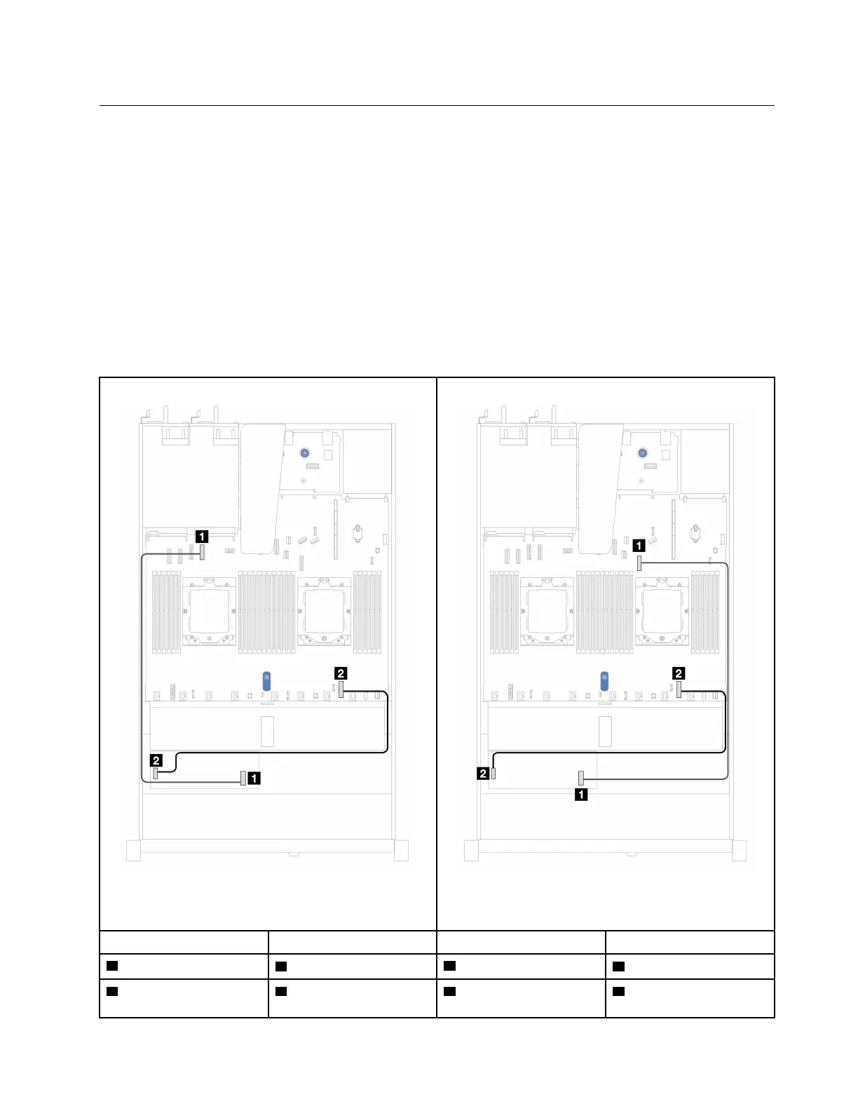
Table 19. Cable routing for CFF RAID adapters
Figure 113. CFF RAID adapter cabling with two
processors installed
Figure 114. CFF RAID adapter cabling with one processor
installed
From To From To
1 MB input
1 PCIe connector 4
1 MB input
1 PCIe connector 7
2 Power 2 Internal RAID power
connector
2 Power 2 Internal RAID power
connector
Chapter 6. Internal cable routing 159

 Loading...


