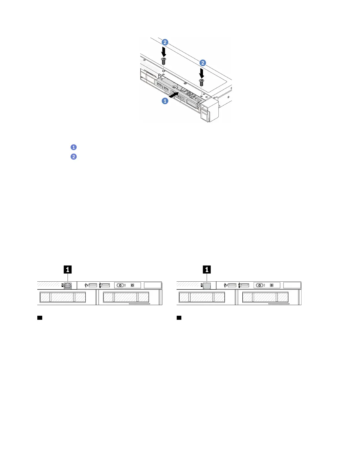
Figure 39. Front I/O module installation
a. Insert the front I/O module into the front chassis.
b.
Install the screws to secure the front I/O module in place.
After you finish
If you are instructed to return the component or optional device, follow all packaging instructions, and use
any packaging materials for shipping that are supplied to you.
Install the external LCD cable (4 x 3.5'' chassis)
Use this information to install the external LCD cable.
In the 4 x 3.5'' chassis configuration, the external LCD cable is an optional part. You can choose either install
or remove the cable according to your actual needs. Refer to the location of external LCD cable from the
front view as below:
1 The external LCD cable connector
Figure 40. A front view with the cable installed
1 A filler for external LCD cable connector
Figure 41. A front view with a filler installed
Note: Before installing the cable, remove the filler first; after removing the cable, install the filler afterwards.
About this task
The following illustrates how to remove the external LCD cable from the chassis.
Attention:
• Read
“Installation Guidelines” on page 35 and “Safety inspection checklist” on page 36 to ensure that you
work safely.
66 ThinkSystem SR645 V3 User Guide

 Loading...


