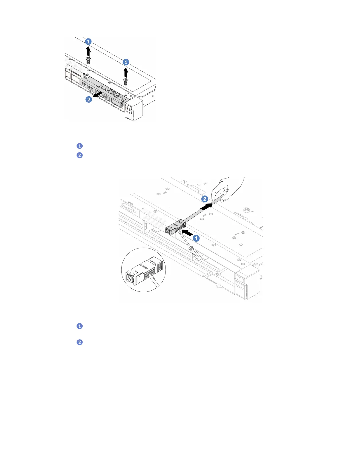
Figure 37. Front I/O module removal
a. Remove the screws that secure the front I/O module.
b.
Slide the front I/O module out of the front chassis.
Step 5. Remove the external LCD cable.
Figure 38. Removal of the external LCD cable
a. Poke the connector latch with the tip of a flat-blade screwdriver (3 or 4 mm) to disengage
the connector from the chassis.
b.
Pull out the cable from the back side.
Step 6. Install the front I/O module back to the chassis.
Chapter 5. Hardware replacement procedures 65

 Loading...


