Page 27
©2013 Technical Marine Service, Inc. LC-100 V2.97
Electrical Connections
General
Depending upon options ordered there are
five possible locations for electrical
connections in the LevelCom 100. 115 Volt
AC power wiring should be separated from
any signal or low-voltage control wiring.
Generally the 115 Volt AC wires would utilize
the upper conduit, and signal or low-voltage
wiring, if any, would use the lower conduit.
Secure wires with plastic cable ties to the
strain relief plate at the top of the enclosure
above the main controller circuit board.
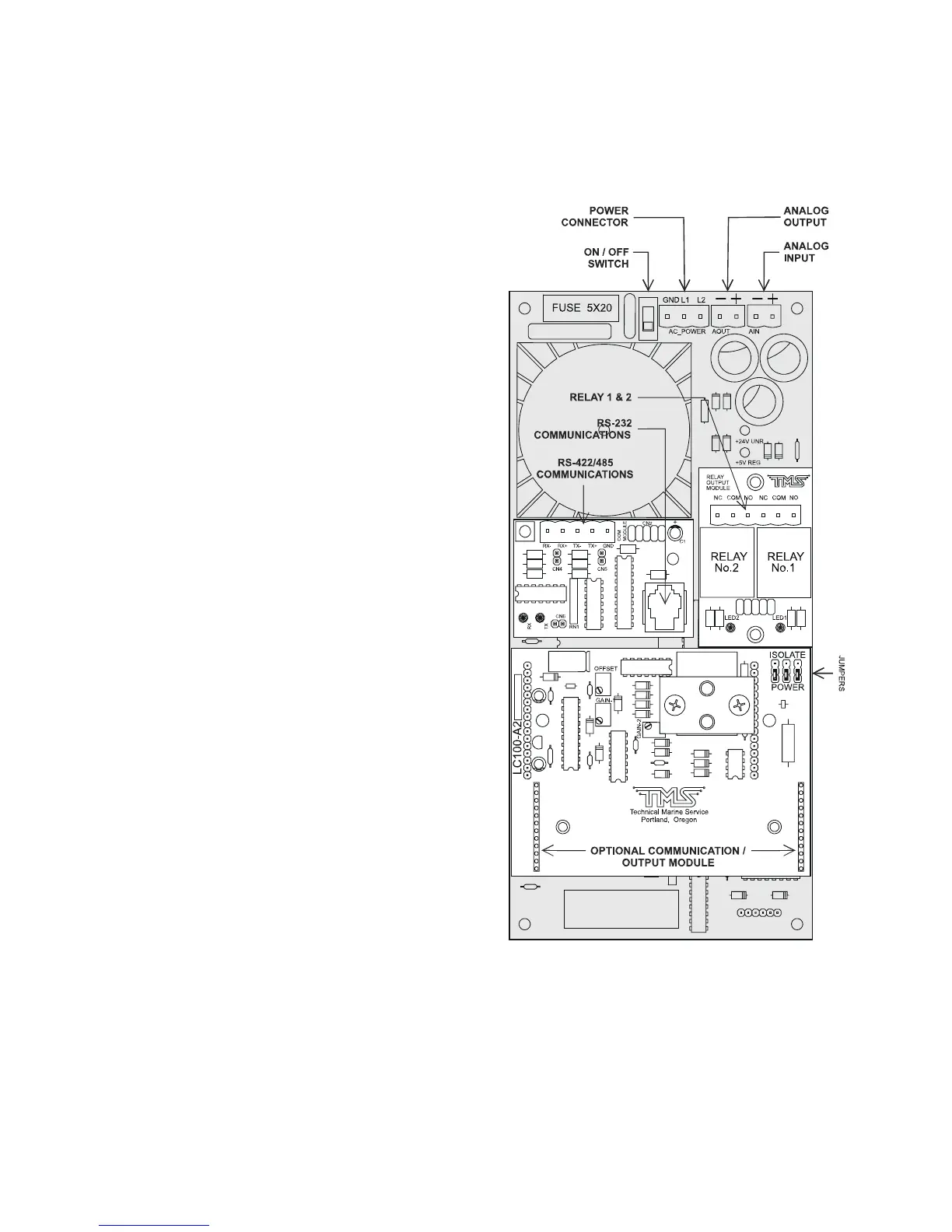
115VAC
115 VAC connections are made via the three-
point connector labeled AC POWER at the
top center of the circuit board (See Figure
13). The three-point connector is actually a
plug and socket. Grasp the plug firmly and
pull it off the board. Note the printing on the
circuit board above the socket, which reads
[GND] [L1] [L2].
Note the enclosure ground “GND” stud
located on the inside of the enclosure,
immediately to the right of the 3 capacitors on
the main CPU board. This stud should be
wired to ground; it is intended as a protective
earth connection. There is not adequate
connection between the circuit boards and
the case to insure a proper case protective
ground.
The LevelCom 100 power switch is located to
the left of the 115 VAC connector. Power ON
is the up position (closest to the edge of the board).
Figure 13 General Electrical Wiring