Page 28
©2013 Technical Marine Service, Inc. LC-100 V2.97
It is important to segregate low voltage wiring, typically 24VDC from the high voltage wiring.
Power wiring is usually 115 VAC. If the optional Relay Module is installed it is possible that
wiring to the relays is also 115 VAC. This must be verified before wiring the unit. Low
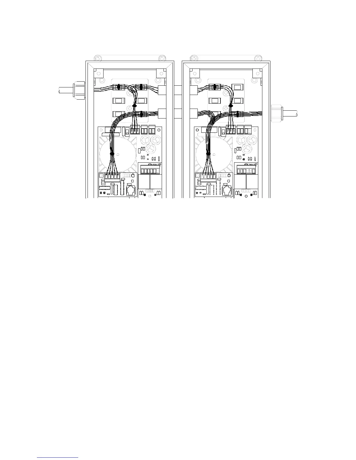
voltage wiring and high voltage wiring should enter the LevelCom 100 through separate
strain reliefs, possibly from opposite sides of the box. Figure 14 shows how this might be
done for a pair of LevelCom 100s mounted on a panel. The interconnect kit is used to
establish a wiring path between the two boxes. In this example there is power wiring and
communication wiring. The power wiring uses the upper wireway, and is banded to the strain
relief plate. The wires to the main power connectors arch over the communication wire
bundle. The communication wiring uses the lower wireway and is banded to the strain relief
plate.
24VDC
If your machine is built with the 24VDC input power option the 24VDC power connections are
made via the three-point connector labeled AC POWER at the top center of the circuit board
(See Figure 13). In place of the transformer on the controller circuit board there will be a
small circuit board with a DC to DC converter. There is a label on this circuit board
describing the wiring for this option. Note that the GND connection is for system ground and
not the 24V power supply return.
Figure 14 Panel Mount Wiring Example
AC_POWER AOUT AIN
+5V REG
+2 4V U N R
FUS E 5X20
RN1
CN6
CN4 CN5
CN2
C1
COM
MODULE
TX
RX
RELAY
No .2
REL AY
No. 1
LED2 LED1
REL AY
LOW VOLTAGE
AC_POWER AOUT AIN
+5V REG
+24V UNR
FUSE 5X20
RN1
CN6
CN4 CN5
CN2
C1
COM
MODULE
TX
RX
RELAY
No.2
REL AY
No .1
LED2 LED1
RELAY
HIGH VOLTAGE