Page 90
©2013 Technical Marine Service, Inc. LC-100 V2.97
Appendix A
Serial Network Wiring Diagrams
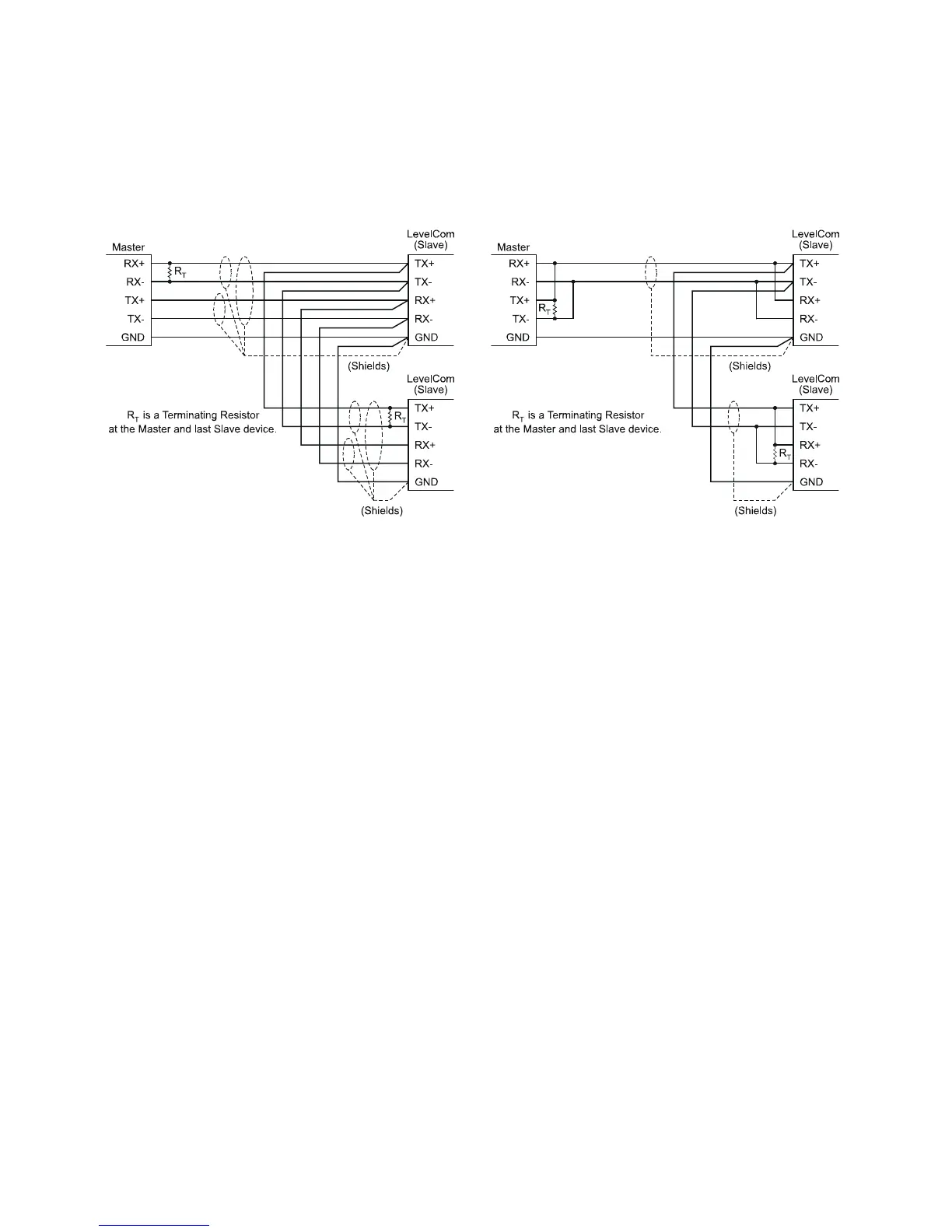
The above diagrams show the wiring for various RS485 installations. Both 5 wire and three
wire networks are supported. See the documentation on the master device for the
connections. There is not a standard pinout for 9 pin D subminiature connectors so none is
shown here. If you are using a plug in expansion card in a PC the documentation for the
card will show the correct pinout for the connectors.
RS-485 connections may be wired to single nodes or multiple nodes. These drawings show
multiple node connections
For low speed communications terminating resistors may not be needed, check the
documentation with the computer interface for the value of these resistors if needed.
Figure 26 5 Wire RS-422/485 Wiring
Figure 25 3 Wire RS-422/485 Wiring