Page 73
©2013 Technical Marine Service, Inc. LC-100 V2.97
the location).
3. Enter the LevelCom 100 configuration
interface. Access the CALIBRATE
menu and select “FIELD CAL”. Press
ENTER. The output from the pressure
sensor will be displayed. This is a
number directly from the hardware. It is
not scaled into any engineering units.
4. For 15 PSI and 30 PSI sensors the
number should be near 50, for 100 PSI
sensors the number should be near 80.
For 100 PSI 16 bit sensors the situation
is more complicated. See page 75 for
special instructions if this is the case.
Adjust the zero pot to get the correct
reading. Press ACK and proceed to step 5.
5. Adjust the OFFSET potentiometer on the pressure sensor circuit board until the display
reads 50 if the for a 15 PSI or 30 PSI sensor, or 80 for a 100 PSI sensor (Refer to Figure
23 for the location of the OFFSET potentiometer). Press ACK when this step is done and
proceed to step 5.
6. Using the appropriate tubing and fittings, connect the calibration gauge and the hand
pump to the two opposing sides of a “T” fitting. Connect the center of the “T” fitting to the
PORT 1 DRAIN on the LevelCom 100.
7. Using the hand pump and calibration gauge apply the following pressure to the LevelCom
100 based on the pressure sensor type installed:
15 PSI 400.0" H
2
O (14.45 psi)
30 PSI 800.0" H
2
O (28.90 psi)
100 PSI 1200.0" H
2
O (43.35 psi)
100 PSI 16 bit 2400.0" H
2
O (86.70 psi)
The instrument will now read the applied pressure in inches of water to an accuracy of 0.1”.
If the reading is different from this value adjust the GAIN-1 potentiometer until the correct
reading shows on the display, agreeing with the reading on the calibration gauge. (Refer to
Figure 23 for the location of the GAIN-1 potentiometer)
Note: It is very important here that the hand pump and calibration gauge setup does not leak.
It is very difficult to do this adjustment correctly if there are even small leaks in the calibration
equipment.
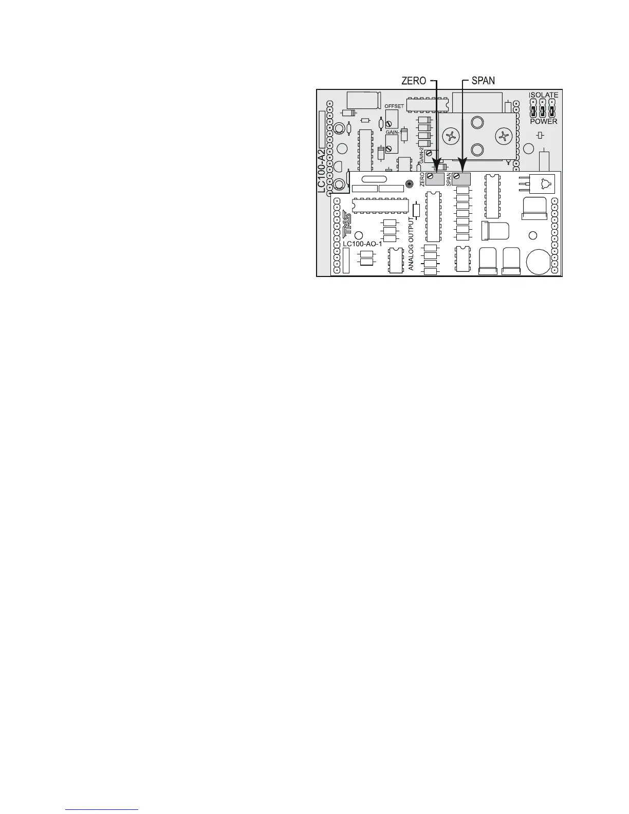
Figure 24 LC100-AO-1 Calibration Potentiometers